Basics Tutorial 4: Routing Signals
Introduction
In this tutorial we'll look at different ways to route MSP audio connections, as well as review sending messages remotely within Max with a focus on how this can be useful in signal network design. Along the way we'll learn about how gain can be expressed in decibels and how the phasor~ object works.
Remote signal connections: send~ and receive~
The patch cords that connect MSP objects look different from normal patch cords because they actually do something different. They describe the order of calculations in a signal network. These connected objects will be used to calculate a whole block of samples for the next portion of sound output by your computer.
Max objects can communicate remotely without patch cords by using the send and receive objects (and some similar objects such as value and pv). You can also use semicolons in message boxes to transmit values to receive objects by their name. You can transmit MSP signals remotely as well. Rather than using normal send and receive objects, however, two MSP objects exist specifically for remote transmission of signals: send~ and receive~.
The two objects send~ and receive~ work very similarly to send and receive, but are only for use with MSP signals. Max will allow you to connect normal patch cords to send~ and receive~, but only signals will get passed through send~ to the corresponding receive~.
Similar to how the names of send and receive can be shortened to s and r, the names of send~ and receive~ can be shortened to s~ and r~.
There are a few important differences between the Max objects send and receive and the MSP objects send~ and receive~.
- A Max message can be sent to a receive object from several other objects besides send, such as float, forward, grab, if, int, and message; receive~ can receive a signal only from a send~ object that shares the same name.
- If receive has no typed-in argument, it has an inlet for receiving messages to set or change its name; receive~ also has an inlet for that purpose, but is nevertheless required to have a typed-in argument to give it an initial destination name.
- The Max send object, once created, cannot change destinations (the Max forward object does this). The MSP send~ can change destinations with a message.
Examples of each of these usages can be seen in the tutorial patch.
Routing a signal: gate~
The MSP object gate~ works very similarly to the Max gate object. Just as gate is used to direct messages to one of several destinations, or to shut the flow of messages off entirely, gate~ directs a signal to different places, or shuts it off from the rest of the signal network.
In the example patch, the gate~ objects are used to route signals to the left audio output, the right audio output, both, or neither, according to what number is received from the umenu object.
It is worth noting that changing the chosen outlet of a gate~ while an audio signal is playing through it can cause an audible click because the signal shifts abruptly from one outlet to another. To avoid this, you should generally design your patch in such a way that the gate~ object's outlet will only be changed when the audio signal going through it is at zero or when audio is off. (No such precaution was taken in this tutorial patch.)
The closed outlets of gate~ do not stop sending signals, they continue to send a signal with a constant value of 0. If the idea of a constant signal seems strange to you, think of it as 44,100 0s a second.
Wave interference
It's a fundamental physical fact that when we add together two sinusoidal waves with different frequencies we create interference between the two waves. Since they have different frequencies, they will usually not be exactly in phase with each other; at some times they will be sufficiently in phase that they add together constructively, but at other times they add together destructively, canceling each other out to some extent. They only arrive precisely in phase with each other at a rate equal to the difference in their frequencies. For example, a sinusoid at 1000 Hz and another at 1002 Hz come into phase exactly 2 times per second. In this case, they are sufficiently close in frequency that we don't hear them as two separate tones. Instead, we hear their recurring pattern of constructive and destructive interference as beats occurring at a sub-audio rate of 2 Hz, a rate known as the difference frequency or beat frequency. (Interestingly, we hear the two waves as a single tone with a sub-audio beat frequency of 2 Hz and an audio frequency of 1001 Hz.)
When the example patch is opened, a loadbang object sends initial frequency values to the two cycle~ objects in the patch, setting them to 1000 Hz and 1002 Hz; so we expect that these two tones sounded together will cause a beat frequency of 2 Hz. It also sends initial values to the umenu objects which in turn set the gate~ objects, directing one tone to the left audio output and one to the right audio output. A fourth value called is also set. All of this is accomplished by using a box to remotely set values picked up by Max receive objects in the patcher.
Amplitude and relative amplitude
The slider marked ‘Volume’ has been set to have a range of 101 values, from to , which makes it easy to convert its output to a float ranging from to just by dividing by 100. (The decimal point in argument typed into the / object ensures a float division.)
The *~ objects use the specified amplitude value to scale the audio signal before it goes to the ezdac~. If both oscillators get sent to the same inlet of ezdac~, their combined amplitude will be 2. Therefore, it is prudent to keep the amplitude scaling factor at or below 0.5. For that reason, the amplitude value which the user thinks of as being between 0 and 1 is actually kept between 0 and 0.5 by the * object below the slider.
Because of the wide range of possible audible amplitudes, it may be more meaningful in some cases to display volume numerically in terms of the logarithmic scale of decibels (dB), rather than in terms of absolute amplitude. The decibel scale refers to relative amplitude, i.e. the amplitude of a signal relative to some reference amplitude. The formula for calculating amplitude in decibels is:
where A is the amplitude being measured and Aref is a fixed reference amplitude.
The AtodB object uses a reference amplitude of 1 in the formula shown above, and converts the amplitude to dB. If you turn off the audio (for safety) and raise the slider to its maximum value (ensuring an output of ), you will see the decibel output of the AtodB object read (i.e. unity gain). Each halving of the amplitude in the slider is approximately equal to a 6 dB reduction in decibels.
Constant signal value: sig~
Most signal networks require some changing values (such as an amplitude envelope to vary the amplitude over time) and some constant values (such as a frequency value to keep an oscillator at a steady pitch). In general, one provides a constant value to an MSP object in the form of a message, as we have done in these examples when sending a frequency in the left inlet of a cycle~ object.
However, there are some cases when one wants to combine both constant and changing values in the same inlet of an MSP object. Inlets that accept either a or a (such as the left inlet of cycle~) do not successfully combine the two. In general, MSP objects will ignore a floating-point value in deference to a signal input. As a result, it's necessary to have an object that outputs a constant value as a signal if you need to combine a fixed and changing value in an MSP signal chain.
One way to combine a numerical Max message (an or a ) with a signal is to convert the number into a steady signal with the sig~ object. The output of sig~ is a signal with a constant value, determined by the number received in its inlet.
In the example patch, combines a constant frequency (supplied as a to sig~) with a varying frequency offset (signal values coming in from a receive~ object called ). The sum of these signals will be the frequency of the oscillator at any given instant.
Changing the phase of a waveform: phasor~
For the most part, the phase offset of an isolated audio wave doesn't have a substantial effect perceptually. For example, a sine wave in the audio range sounds exactly like a cosine wave, even though there is a theoretical phase difference of a quarter cycle. For that reason, we have not been concerned with the rightmost phase inlet of the cycle~ object until now.
However, there are some very useful reasons to control the phase offset of a wave. For example, by leaving the frequency of cycle~ at , and continuously increasing its phase offset, you can change its instantaneous value (just as if it had a positive frequency). The phase offset of a sinusoid is usually referred to in degrees (a full cycle is 360°) or radians (a full cycle is 2*π radians in length). In the cycle~ object, phase is referred to in wave cycles; so an offset of π radians is 1/2 of a cycle, or . In other words, as the phase varies from 0 to 2π radians, it varies from to wave cycles. This way of describing the phase is handy since it allows us to use the common signal range from 0 to 1.
So, if we vary the phase offset of a stationary (0 Hz) cycle~ object continuously from 0 to 1 over the course of one second, the resulting output is a cosine wave with a frequency of 1 Hz.
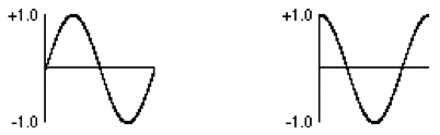
The phasor~ object is a very useful MSP signal generator that simply outputs a ramp from to at a given frequency. As with the cycle~ object, it's frequency can be set by an argument to the object, a floating-point value in its left inlet, or a signal. Later in our tutorial, we'll hear what it sounds like (it's a sawtooth wave, and not an especially pleasant one), but for now let's use it for changing the phase (hence phasor~ of the cycle~ object in the lower-left of the tutorial patcher.
The cycle~ in the bottom-left of the patcher is modulating the cycle~ object in the upper-right by adding a value to its current (constant) frequency, set by the sig~ object.
Receiving a different signal
The remaining portion of the tutorial patch exists simply to demonstrate the use of the message to the receive~ object. This is another way to alter the signal flow in a network. As with the send~ object, you can change the name of the receive~ object with a message, instructing it to get its input from a different send~ object (or objects).
Summary
It is possible to make signal connections without patch cords by using the MSP objects send~ and receive~, which are similar to the Max objects send and receive. The message can be used to change the name of a send~ or receive~ object, thus switching how signals are routed. Signal flow can be routed to different destinations within a patcher, or shut off entirely, using the gate~ object, which is the MSP equivalent of the Max object gate.
The cycle~ object can be used not only for periodic audio waves, but also for sub-audio control functions: you can read through the waveform of a cycle~ object at any rate you wish by keeping its frequency at 0 Hz and changing its phase continuously from to . The phasor~ object is appropriate for changing the phase of a cycle~ waveform in this way; you could also use a line~ object to create a ramp that goes through the object's wavetable.
The sig~ object converts a number to a constant signal; it receives a number in its inlet and sends out a signal of that value. This is useful for combining constant values with varying signals. Mixing together tones with slightly different frequencies creates interference between waves, which can create beats and other timbral effects.
See Also
| Name | Description |
|---|---|
| gate~ | Route a signal to one of several outlets |
| receive~ | Signals can be received from any loaded patcher, without patch cords |
| send~ | Send signals without patch cords |
| sig~ | Convert numbers into audio signals |
| phasor~ | Generate sawtooth signals |