Filter Tutorial 4: Subtractive Synthesis
In this chapter, we'll look at using filters creatively with a group of MSP audio generators that create different kinds of noise~. Noise generation is a core component of subtractive synthesis, a sound design methodology that works by taking complex signsl and sculpting them with filters, subtracting energy from the original signal (compare this with additive synthesis, which works in the opposite fashion). Along the way, we'll discuss ways to shape this noise using an object that creates and controls a bank of parallel filters.
Noise
Take a look at our tutorial patcher. It consists of three patcher regions. If we look at the area labeled , we can see that we have three new MSP objects connected through *~ objects to the dac~.
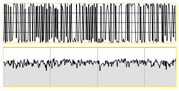
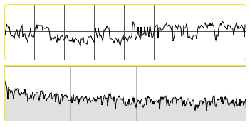
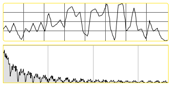
The noise~, pink~, and rand~ objects all generate noise at a signal rate. Noise, at its essence, is a type of random number generation; as a result, these objects behave in a similar manner to Max objects such as random and drunk.
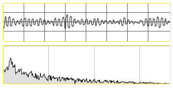
The noise~ object generates white noise, which means that all possible frequencies in the audio spectrum are equally represented over time. The process of generating white noise digitally is quite simple: every sample, pick a random number between and :
The pink~ object generates pink noise, which means that every octave in the audio spectrum has equal weight. This is sometimes referred to as 1/f noise, as the probability of a frequency occuring is the inverse of its value, e.g. frequencies of 100 Hz are twice as probable as 200 Hz. The aural difference between the two is fairly obvious: white noise has far more high frequency content and sounds 'harsher' than pink noise:
The rand~ object is a random number generator that generates a signal, picking a new random value for that signal at a variable rate. It takes an argument (or a value at its inlet) to set the frequency of the random number selection. A frequency of makes the object indistinguishable from white noise. This allows us to create band-limited noise that has an upper boundary we can specify:
Filtering noise
Because noise has such broadband frequency content, it can be filtered and sculpted to create very precise timbres. The compositional technique of subtractive synthesis relies on this attribute of noise generation; it's often easier (or more efficient) to start with noise and filter it down then attempt to create the desired timbre through adding oscillators.
Patcher area contains a noise~ object sending its signal into a lores~ filter. The frequency of the lowpass filter is being modulated by a phasor~, which we've scaled to ramp between and at the frequency we specify. As a result, the cutoff frequency of the filter sweeps at regular intervals. This is an example of an LFO, or low-frequency oscillator, being used to modulate a parameter of an audio processing system. As you can hear, the lores~ object attenuates the high frequencies output from the noise~ object. In addition, the resonance value of the lores~ causes the filter to have a peak just below its cutoff frequency, giving a notably 'pitched' sound to the filtered noise.
Banks of filters
The fffb~ object stands for Fast, Fixed, Filter Bank. Unlike the cascade~ object, which implements a number of biquad~ filters in series, the fffb~ object arranges a number of reson~ objects in parallel, which is to say that the settings of one filter will not affect any of the others. The fffb~ object takes a number of arguments which set its behavior: the number of filters, the base frequency of the filter bank, the ratio between filters, and the Q of the filters. All of the parameters of the object with the exception of the number of filters can be changed with Max messages; the number is fixed because, as we can see, each filter connects to a separate outlet. This allows us to create filter banks, where we can 'tap' each bandpass filter individually:
The value from the dial is interpreted as a MIDI pitch, converted to frequency (via the mtof) object, and used to format the message to the fffb~ object. The message takes two arguments: the center frequency of the first (lowest) filter, and the ratio between it and subsequent filters. The letter , when used as the ratio, tells the fffb~ object to set the filters in the bank to harmonic multiples of the base frequency. So the message would set our ten filters up to be centered to Hz increments.
We can easily set our filters in a frequency ratio other than a harmonic series. Setting our base frequency to and our ratio to results in a bank of ten filters set to the frequencies Hz, respectively. Other popular ratios include 1.4142 (21/2) and 1.25992 (21/3) for half octave and one third octave spacing. As with the reson~ object, we have direct control over the Q of these filters. A Q of results in a bandwidth of 1/100 the frequency, creating narrow, pitched filters.
The fffb~ object takes many other messages, enabling us to set the filters not in ratio at all. Sending lists in the format allows us to set each filter in the bank individually. In our example, we've set the ten filters to frequencies from a musical chord.
Metering
Next to each gain~ slider in patcher area is a user-interface object that registers the amplitude of the signal connected to it. These meter~ objects allow us to see the level from each filter in the fffb~ pre-fader, i.e. before we listen to it.
Because the fffb~ object works in parallel, the output gain of all the filters in the bank will typically be greater than the gain of the incoming signal. Depending on the Q values and the frequencies used, the potential volume output from the fffb~ can be quite high. The meter~ object lets you observe your volumes visually in the patcher window before you listen (and potentially hurt your ears).
Summary
MSP has three simple-to-use noise generator objects, which generate white noise (noise~), pink noise (pink~), and band-limited random signals (rand~). These objects are ideal candidates for filtering. The fffb~ object implements a fixed filter bank of parallel bandpass filters which can be controlled via ratios of a base frequency or individually. The meter~ object allows you to visually see the amplitude of any part of the MSP signal path, and is incredibly useful for metering and debugging your audio patchers.
See Also
| Name | Description |
|---|---|
| noise~ | Generate white noise |
| pink~ | Pink noise generator |
| rand~ | Band-limited random signal |
| fffb~ | Fast fixed filter bank |
| meter~ | Visual peak level indicator |