Examples
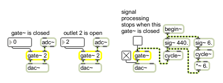
gate~ routes the input signal to one of its outlets or shuts it off entirely
Route a signal to one of several outlets
| Name | Type | Opt | Description |
|---|---|---|---|
| number-of-outlets | int | opt | The first argument specifies the number of outlets. The default is 1. The second argument sets the outlet that will initially send out the input signal. The default is 0, where all signals are shut off and zero signals are sent out all outlets. If a signal is connected to the left inlet, the second argument is ignored. |
| int | outlet-selected [int] |
In left inlet: Determines the outlet that will send out the signal coming in the right inlet. If the number is or negative, the right inlet is shut off and a zero signal is sent out. If the number is greater than the number of outlets, the signal is sent out the rightmost outlet. If a is connected to the left inlet, gate~ ignores or messages received in its left inlet. |
| signal | In left inlet: If a signal is connected to the left inlet, gate~ operates in a mode that uses signal values to determine the outlet that will receive its input signal (the signal coming in the right inlet). If the signal coming in the left inlet is 0 or negative, the inlet is shut off and a zero signal is sent out. If it is greater than or equal to 1, but less than 2, the input signal goes to the left outlet. If the signal is greater than or equal to 2 but less than 3, the input signal goes to the next outlet to the right, and so on. If the signal in the left inlet is greater than the number of outlets, the rightmost outlet is used. In right inlet: The input signal to be passed through to one of the gate~ object's outlets, according to the most recently received or in the left inlet, or the value of the signal coming in the left inlet. If the signal network connected to the right inlet of gate~ contains a begin~ object -- and a signal is not connected to the left inlet of the gate~-- all processing between the begin~ outlet and the gate~ inlet will be turned off when gate~ is shut off. |
| Name | Description |
|---|---|
| selector~ | Assign one of several inputs to an outlet |
| begin~ | Define a switchable part of a signal network |
| MSP Tutorial 4: Routing Signals | MSP Tutorial 4: Routing Signals |
| MSP Tutorial 22: MIDI Panning | MSP Tutorial 22: MIDI Panning |