Examples
Use rate~ to generate synchronized waveforms or control sources
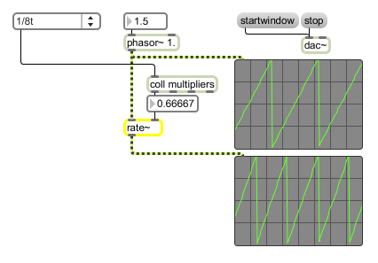
Time-scale the output of a phasor~
| Name | Type | Opt | Description |
|---|---|---|---|
| multiplier | float | opt | The multiplier value used to scale the output signal. |
| int | phase/multiplier [int] |
Converted to in any inlet. |
| float | phase/multiplier [float] |
In left inlet: Sets the phase value for the rate~ object's signal output. In right inlet: The signal multiplier value used to scale the phasor~ signal input. Float values less than 1.0 create several ramps per phase cycle. Numbers greater than 1.0 create fewer ramps. This can be useful for synchronizing multiple processes to a single reference phasor~ object, preserving their ratio relationships. |
| goto | jump-to-value and time-of-action [list] |
In left inlet: The word , followed by a float, causes the rate~ object to jump immediately to the specified value. An optional second argument may be used to specify the time at which to jump to the value (e.g., will output a value of 1.0 at the halfway point of the phasor~ object's input signal ramp). |
| oneshot | loop-flag (0 or nonzero) [int] |
The message will turn on "oneshot"-mode whereby rate~ outputs only one cycle of a ramp. The message will turn "oneshot"-mode off whereby rate~ can cycle through ramps continuously when instructed to do so (i.e. by the message). |
| reset | In left inlet: The word will lock the output to the input on its next reset. It is equivalent to the message . | |
| signal | In left inlet: An input signal from a phasor~ object. The rate~ object time scales the input signal from a phasor~ by a multiplier value. The multiplier value can be specified as an argument or received as a float to the rate~ object's right inlet. | |
| sync | sync-mode-flag (0 through 2) [list] |
In left inlet: The word , followed by a number between 0 and 2 or the words , , or , sets the sync mode of the rate~ object. The sync mode determines whether or not the rate~"in" will stay in phase with the input signal, and the method used for synchronization. When the output of the rate~ object is "in phase," the input and output signals align precisely at the least common multiple of their periods (i.e., they pass through zero and begin a new cycle at precisely the same time). If the signals are in phase, and a new multiplier value is received, the rate~ object changes the frequency of its output ramp accordingly. However, the change in multiplier values means that the two signals may be out of phase. The rate~ object handles this situation in one of three different ways, depending on the sync mode: The sync modes are: : The messages or set the cycle mode of the rate~ object (the default mode). In cycle mode, the rate~ object does not change the phase of its output until the end of the current cycle. When the input ramp reaches its peak and starts over from zero, the rate~ object immediately restarts the output ramp, causing a discontinuity in the output signal, and immediate phase synchronization. : The messages or set the lock mode of the rate~ object. In sync lock mode, the rate~ object performs synchronization whenever a new multiplier is received. The rate~ object immediately calculates the proper ramp position which corresponds to being "in phase" with the new multiplier value, and jumps to that position. : The messages or disables the sync mode of the rate~ object. In this mode rate~ never responds to phase differences; when a new multiplier is received, the rate~ object adjusts the speed of its output ramps and they continue without interruption. Since this mode never introduces a discontinuous jump in the ramp signal, it may be useful if phase is unimportant. |