Examples
Loop through part of a sample treating it as a variable-size wavetable
Variable size wavetable
| Name | Type | Opt | Description |
|---|---|---|---|
| buffer-name | symbol | Obligatory. Names the buffer~ object whose sample memory is used by wave~ for its stored waveform. Note that if the underlying data in a buffer~ changes, the signal output of wave~ will change, since it does not copy the sample data in a buffer~. wave~ always uses the first channel of a multi-channel buffer~. | |
| start and end-points (millisecond-offsets) | float or int | opt | After the buffer~ name argument, you can type in values for the start and end points of the waveform, as millisecond offsets from the beginning of a buffer~ object's sample memory. By default the start point is 0 and the end point is the end of the sample. If you want to set a non-zero start point but retain the sample end as the waveform end point, use only a single typed-in argument after the buffer~ name. The wave~ object uses the buffer~ sampling rate to determine loop points. If a is connected to the start point (middle) inlet, the initial waveform start point argument is ignored. If a is connected to the end point (right) inlet, the initial waveform end point is ignored. An additional optional integer can used to specify the number of channels in the buffer~ file. |
| number-of-output-channels | int | opt | Sets the number of output channels, which determines the number of outlets that the wave~ object will have. The maximum number of signal outputs is 4. If the buffer~ object being played by wave~ has more channels than the number of outputs of wave~, the extra channels are not played. If the buffer~ object has fewer channels, the extra wave~ signal outputs are 0. |
| int | start/end-point [int] |
In middle or right inlets: Numbers can be used instead of signal objects to control the start and end points of the waveform, provided a is not connected to the inlet that receives the number. The wave~ object uses the buffer~ sampling rate to determine loop points. |
| float | start/end-point [float] |
In middle or right inlets: Numbers can be used instead of signal objects to control the start and end points of the waveform, provided a is not connected to the inlet that receives the number. The wave~ object uses the buffer~ sampling rate to determine loop points. |
| (mouse) | Double-clicking on the wave~ object will open a window that displays the audio file loaded in the buffer associated with the object. | |
| interp | interpolation-mode (0 through 2) [int] |
The word , followed by a number in the range 0-2, sets the wavetable interpolation mode. The interpolation modes are: - - No interpolation. Wavetable interpolation is disabled using the interp 0 message. - High-quality linear interpolation (default) - Low-quality linear interpolation. This mode uses the interpolation method found in MSP 1.x versions of the wave~ object. While this mode is faster than mode 1, it cannot play buffer~ objects of arbitrary length and produces more interpolation artifacts. |
| set |
buffer-name [symbol] start-point (millisecond-offset) [float] end-point (millisecond-offset) [float] |
In left inlet: The word , followed by a , sets the buffer~ used by wave~ for its stored waveform. The can optionally be followed by two values setting new waveform start and end points. If the values are not present, the default start and end points (the start and end of the sample) are used. If signal objects are connected to the start and/or end point inlets, the start and/or end point values are ignored. |
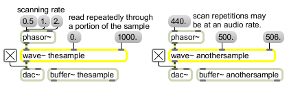
| signal | In left inlet: Input signal values progressing from 0 to 1 are used to scan a specified range of samples in a buffer~ object. The output of a phasor~ can be used to control wave~ as an oscillator, treating the range of samples in the buffer~ as a repeating waveform. However, note that when changing the frequency of a phasor~ connected to the left inlet of wave~, the perceived pitch of the signal coming out of wave~ may not correspond exactly to the frequency of phasor~ itself if the stored waveform contains multiple or partial repetitions of a waveform. You can invert the phasor~ to play the waveform backwards. In middle inlet: The start of the waveform as a millisecond offset from the beginning of a buffer~ object's sample memory. In right inlet: The end of the waveform as a millisecond offset from the beginning of a buffer~ object's sample memory. |
| Name | Description |
|---|---|
| 2d.wave~ | Two-dimensional wavetable |
| buffer~ | Store audio samples |
| buffir~ | buffer-based FIR filter |
| groove~ | Variable-rate looping sample playback |
| phasor~ | Sawtooth wave generator |
| play~ | Position-based sample playback |
| sync~ | Synchronize MSP with an external source |
| MSP Tutorial 15: Variable-length Wavetable | MSP Tutorial 15: Variable-length Wavetable |