A newer version of Max is available. Click here to access the latest version of the documentation

jit.lcd Reference

QuickDraw wrapper (deprecated)

jit.lcd

Description

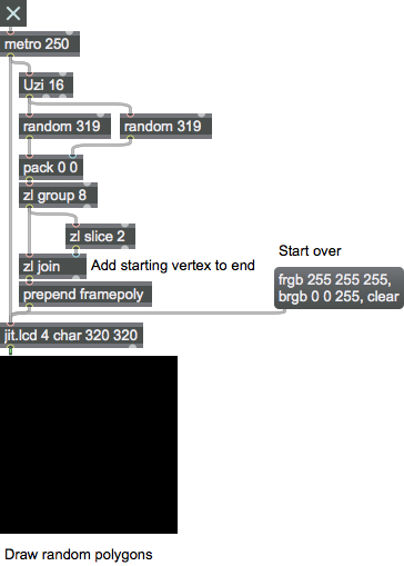
The jit.lcd object is a wrapper for many QuickDraw commands.

Examples

Matrix Operator

matrix inputs:0, matrix outputs:1
Name IOProc Planelink Typelink Dimlink Plane Dim Type
out n/a 1 1 1 4 1 char

More about Matrix Operators

The Jitter MOP

Since the matrix is Jitter's focus, it is not surprising that the majority of Jitter objects fall in this category of Matrix Operators. Every Matrix operator has some number of matrix inputs and some number of matrix outputs. Matrix inputs are referred to by the names "in", "in2", "in3", etc., from left to right, and matrix outputs are referred to by the names "out", "out2", "out3", etc., from left to right--i.e. the names are appended by the input/output number except for the first (leftmost) input and first (leftmost) output which are simply named "in" and "out". We will refer to the input or output name names as the "I/O-name".

Matrix inputs and outputs typically each have their own matrices internally where information is kept. This is necessary because Jitter is an asynchronous framework (i.e. all the matrices don't arrive at all inputs at the same time). Various aspects of matrix inputs and outputs can be set using the command [I/O-name] combined with one of the following suffixes: "_dim" which will set the dimensions of the specified I/O matrix, "_type" which will set the type of the specified matrix, "_planecount" which will set the plane of the specified matrix, or "_name" which will set the name of the specified matrix. There is one special case which does not have an internal matrix and this is the first input "in". This is the case since this special input actually triggers the calculation of the matrix operator, so it doesn't need to be cached until a calulation takes place, unlike the other inputs. Therefore there is no mechanism to set the dim, planecount, type, or name of "in".

Matrix operators accept what we'll refer to as "matrix args"--i.e. [planecount (int)] [ type (symbol)] [dim (int list)]. if these arguments are present, the adapt attribute will be turned off, otherwise it will be turned on. If adapt mode is turned on, each time a matrix is received in the first input, there will also be the equivalent of setting the dim, planecount, and type attributes to that of the input matrix. If the other inputs and outputs are linked to these attributes, this will affect their linked attributes as well. See the "MOP" table to determine which inputs and outputs will be linked to which attributes when adapt mode is turned on. For the leftmost input this is not applicable, and hence all columns are labelled "n/a".

The jit.matrix object is a named matrix which may be used to matrix data storage and retrieval, resampling, and matrix type and planecount conversion operations.

MOP Arguments

planecount [int]

Optional

Explicitly sets the number of planes for the output and any righthand inputs. If this is absent, the Matrix Operator will typically adapt to the lefthand incoming matrix attributes, except for special case operators.

type [symbol]

Optional

Explicitly sets the type of the matrix for the output and any righthand inputs. If this is absent, the Matrix Operator will typically adapt to the lefthand incoming matrix attributes, except for special case operators.

dimensions [list]

Optional

Explicitly sets the dimensions of the matrix for the output and any righthand inputs. If this is absent, the Matrix Operator will typically adapt to the lefthand incoming matrix attributes, except for special case operators.

MOP Attributes

adapt [int]

Matrix adaptation flag (default = 0 if matrix arguments are present, otherwise 1) When the flag is set, the jit.matrix object will adapt to the incoming matrix planecount, type, and dimensions.

[in/out]_dim [32 ints]

The matrix data dimensions (default = 1 1)

[in/out]_name [symbol]

The input or output name of the matrix (default = UID)

[in/out]_planecount [int]

The number of planes in matrix input our output data. Except in special cases, this value is equal to the planecount.

[in/out]_type [symbol]

The input or output matrix data type. Except in special cases, this value is equal to type.

outputmode [int]

Output mode (default = 1 (calculate and output matrix))
0 = No output (no calculation)
1 = Calculate and output the matrix
2 = Pass input (no calculation)
3 = Pass output (no calculation)

type [int]

The matrix data type (default = char
Supported data types are char, long, float32, or float64.

MOP Messages

bang

Equivalent to the outputmatrix message.

clear

Sets all cell values in a matrix to zero.

exportattrs

Arguments

filename [symbol]
Exports an object's current attributes values in XML format. If no filename is specified, a file dialog will open to let you choose a file.

getattributes

Sends a sequence of lists out the object's right outlet describing the object's attributes, one line per attribute. Each line listing takes the form attribute attribute-name get get-value set foo set-value data-type(s) number-of-values .

getstate

Sends a sequence of lists describing the object's state out the object's right outlet, one line per attribute. Each line listing line takes the form attribute-name attribute-value1 attribute-value2 ... attribute-valueN .

importattrs

Arguments

filename [symbol]
Imports attributes specified in XML format to set the object's attributes. If no filename is specified, a file dialog will open to let you choose a file.

jit_matrix

Arguments

matrix-name [symbol]
Handles input for the named matrix. If this messages is received in the left inlet, output is typically triggered. If this message is received in any other inlet, the data is typically cached until the jit_matrix message is received in the left inlet.

outputmatrix

Sends the matrix out the left outlet.

summary

Sends a sequence of lists describing the object and it attributes and messages out the rightmost outlet of the object. The first output line takes the form summary objectname object-name . The second and third lines describe the number of inlets and outlets for the object in the form summary (matrixinputcount/matrixoutletcount) number-of-(inlets/outlets) . The fourth line describes the matrixoutput in the form summary matrixoutput descriptor planelink planelink-value typelink typelink-value dimlink dimlink-value types data-type(s) . Each attribute for the object is then listed, one attribute per line. Each line listing takes the form summary attribute attribute-name attribute-value1 attribute-value2 ... attribute-valueN .

Attributes

Common Box Attributes

annotation [symbol]

Sets the text that will be displayed in the Clue window when the user moves the mouse over the object.

background [int] (default: 0)

Adds or removes the object from the patcher's background layer. background 1 adds the object to the background layer, background 0 removes it. Objects in the background layer are shown behind all objects in the default foreground layer.

color [4 floats]

Sets the color for the object box outline.

fontface [int]

Sets the type style used by the object. The options are:

plain
bold
italic
bold italic Possible values:

0 = 'regular'
1 = 'bold'
2 = 'italic'
3 = 'bold italic'

fontname [symbol]

Sets the object's font.

fontsize [float]

Sets the object's font size (in points). Possible values:

'8'
'9'
'10'
'11'
'12'
'13'
'14'
'16'
'18'
'20'
'24'
'30'
'36'
'48'
'64'
'72'

hidden [int] (default: 0)

Toggles whether an object is hidden when the patcher is locked.

hint [symbol]

Sets the text that will be displayed in as a pop-up hint when the user moves the mouse over the object in a locked patcher.

ignoreclick [int] (default: 0)

Toggles whether an object ignores mouse clicks in a locked patcher.

jspainterfile [symbol]

JS Painter File

patching_rect [4 floats] (default: 0. 0. 100. 0.)

Sets the position and size of the object in the patcher window.

position [2 floats]

g/s(set)

Sets the object's x and y position in both patching and presentation modes (if the object belongs to its patcher's presentation), leaving its size unchanged.

presentation [int] (default: 0)

Sets whether an object belongs to the patcher's presentation.

presentation_rect [4 floats] (default: 0. 0. 0. 0.)

Sets the x and y position and width and height of the object in the patcher's presentation, leaving its patching position unchanged.

rect [4 floats]

g/s(set)

Sets the x and y position and width and height of the object in both patching and presentation modes (if the object belongs to its patcher's presentation).

size [2 floats]

g/s(set)

Sets the object's width and height in both patching and presentation modes (if the object belongs to its patcher's presentation), leaving its position unchanged.

textcolor [4 floats]

Sets the color for the object's text in RGBA format.

textjustification [int]

Sets the justification for the object's text. Possible values:

0 = 'left'
1 = 'center'
2 = 'right'

varname [symbol]

Sets the patcher's scripting name, which can be used to address the object by name in pattr, scripting messages to thispatcher, and the js object.

Messages

ascii

Arguments

character [int]
Writes the ASCII character specified by the character argument at the current pen location using the current font and textmode, then moves the pen position to the right of that character. Numbers that exceed the 0-255 range are restricted to that range with a modulus operation.

brgb

Arguments

red [int]
green [int]
blue [int]
Sets the current background color. All values should be in the range 0-255.

clearpicts

The word clearpicts, followed by a symbol, deletes all of an lcd object's named pictures from memory so that they can no longer be drawn. To remove the images from the lcd object's display, the command should be followed by a clear message.

clipoval

Arguments

left [int]
top [int]
bottom [int]
right [int]
Clips drawing commands to the oval specified by left top right bottom The arguments are specified in pixels, relative to the top left corner of the viewing area.

clippoly

Arguments

x/y int pairs [list]
Clips drawing commands to the polygon specified by the up to 254 x/y-pairs arguments. These integer pairs are specified in pixels, relative to the top left corner of the viewing area.

cliprect

Arguments

left [int]
top [int]
bottom [int]
right [int]
Clips drawing commands to the rectangle specified by left , top , right , and bottom arguments. These integer arguments are specified in pixels, relative to the top left corner of the viewing area.

cliproundrect

Arguments

left [int]
top [int]
bottom [int]
right [int]
horizontal-roundness [int]
vertical-roundness [int]
Clips drawing commands to the rounded rectangle specified by left , top , right , bottom , horizontal-roundness , and vertical-roundness arguments. These integer arguments are specified in pixels, relative to the top left corner of the viewing area.

color

Arguments

color-index [int]
Sets the current pen color to the value specified by the color-index argument.

deletepict

Arguments

any symbol [list]
The word deletepict, followed by a symbol, deletes the named the picture from memory so that it can no longer be drawn. To remove the image from the lcd object's display, the command should be followed by a clear message.

drawpict

Arguments

pict-name [symbol]
x-offset [int]
y-offset [int]
width [int]
height [int]
src-x-offset [int]
src-y-offset [int]
src-width [int]
src-height [int]
Draws the named picture or matrix. A destination rectangle into which the picture is scaled and drawn may optionally be specified by the x-offset , y-offset , width , and height integer arguments. A source rectangle that specifies the area of the picture to use in the operation may also be optionally specified by the src-x-offset , src-y-offset , src-width , and src-height integer arguments. The position of the destination and source rectangles are relative to the top left corner of the jit.lcd object's display area. Unless otherwise specified, both rectangles are set to be the same size as the picture. All arguments are optional and default to zero. The current penmode will used as the transfer mode.

font

Arguments

mutex group
font-id [int]
font-name [symbol]
endmutex group
font-size () [int]
Sets the current font name and size. Fonts can be specified by either their ID number or name. Font size is specified in points.

framearc

Arguments

left [int]
top [int]
bottom [int]
right [int]
start-angle [int]
arc-length [int]
mutex group
color-index [int]
red [int]
green [int]
blue [int]
endmutex group
Paints the outline of an arc. The left , top , right , and bottom arguments describe the top and bottom extremities in pixels of an oval across which the arc will be drawn, and the start-angle and arc-length arguments describe the position of the arc with respect to the oval. The location of the oval/arc is relative to the top left corner of the jit.lcd object's display area. A color may also optionally be specified using a single number that selects a color from Max's color palette (similar to the color message), or by using three additional numbers that describe an RGB value (similar to the frgb message). The width of the line segment describing the arc is set using the pensize message to the jit.lcd object.

frameoval

Arguments

left [int]
top [int]
bottom [int]
right [int]
mutex group
color-index [int]
red [int]
green [int]
blue [int]
endmutex group
Draws the unfilled outline of an oval. The left , top , right , and bottom integer arguments describe the top and bottom extremities in pixels of the oval. The location of the oval is relative to the top left corner of the jit.lcd object's display area. Optional additional arguments to specify the color of the border may also follow. If a single integer argument is used, it specifies a color from Max's color palette. Three integer arguments specify an RGB color. The width of the border of the oval is set using the pensize message to the jit.lcd object.

framepoly

Arguments

x/y int pairs [list]
Draws the unfilled outline of a polygon specified by up to 254 integer x/y-pair arguments. Each integer pair specifies a pixels relative to the top left corner of the jit.lcd object's display area. A polygon is closed by specifying an x/y pair having the same values as the first integer pair. The width of the border of the polygon is set using the pensize message to the jit.lcd object.

framerect

Arguments

left [int]
top [int]
bottom [int]
right [int]
mutex group
color-index [int]
red [int]
green [int]
blue [int]
endmutex group
Draws the unfilled outline of a rectangle specified by the left , top , right , and bottom integer arguments. The edge positions are specified as pixels relative to the top left corner of the jit.lcd object's display area. Optional additional arguments to specify the color of the border may also follow. If a single integer argument is used, it specifies a color from Max's color palette. Three integer arguments specify an RGB color. The width of the border of the rectangle is set using the pensize message to the jit.lcd object.

frameroundrect

Arguments

left [int]
top [int]
bottom [int]
right [int]
horizontal-roundness [int]
vertical-roundness [int]
mutex group
color-index [int]
red [int]
green [int]
blue [int]
endmutex group
Draws the unfilled outline of a rounded rectangle. The left , top , right , and bottom integer arguments describe the top and bottom extremities of the rectangle, and the The horizontal-roundness and vertical-roundness] integer arguments specify the amount of corner rounding in pixels. The location of the rounded rectangle is relative to the top left corner of the jit.lcd object's display area. Optional additional arguments to specify the color of the border may also follow. If a single integer argument is used, it specifies a color from Max's color palette. Three integer arguments specify an RGB color. The width of the border of the rectangle is set using the pensize message to the jit.lcd object.

frgb

Arguments

red [int]
green [int]
blue [int]
Sets the current foreground color. All arguments should be in the range 0-255.

getpenloc

Sends the x and y coordinates of the current pen location out the right outlet of the object as a list in the form penloc x-offset y-offset . The numbers represent local coordinates relative to the top left corner of the jit.lcd object's display area. The first number is the number of pixels to the right of that corner, and the second number is the number of pixels down from that corner.

getpixel

Arguments

x-offset [int]
y-offset [int]
Sends the color of the pixel specified by the x and y offset arguments and the coordinates out the object's right outlet as a list in the form pixel red green blue x-offset y-offset . The three color values should be in the range 0-255. The pixel location is specified relative to the top left corner of the jit.lcd object's display area. If a pixel is out of range, the getpixel message will output pixel 0 0 0 x y, where x and y are the out of range location specified.

line

Arguments

x-offset [int]
y-offset [int]
Draws a line from the current pen position to the relative point specified by two integer x-offset and x-offset arguments. The endpoint of the line becomes the new pen position. Positive values for the x-offset and x-offset arguments draw the line to the right or down, and negative arguments draw up or to the left.

linesegment

Arguments

x-start [int]
y-start [int]
x-end [int]
y-end [int]
mutex group
color-index [int]
red [int]
green [int]
blue [int]
endmutex group
Draws a line segment. The x-start , y-start , x-end , and y-end arguments specify the start and end points of the line segment. The location of the start and end points is relative to the top left corner of the jit.lcd object's display area. Optional additional arguments to specify the color of the line segment may also follow. If a single integer argument is used, it specifies a color from Max's color palette. Three integer arguments specify an RGB color. The width of the line segment is set using the pensize message to the jit.lcd object.

lineto

Arguments

x-offset [int]
y-offset [int]
Draws a line from the current pen position to the relative point specified by two integer x-offset and x-offset arguments. Positive values for the x-offset and x-offset arguments draw the line to the right or down, and negative arguments draw up or to the left.

move

Arguments

x-offset [int]
y-offset [int]
Moves the pen position relative to its current location. The new location is specified by the two integer x-offset and x-offset arguments. Positive values for the x-offset and x-offset arguments move the pen position to the right or down, and negative arguments move it up or to the left.

moveto

Arguments

x-offset [int]
y-offset [int]
Sets the pen position at which the next graphic instruction will be drawn. The new location is specified by the two integer x-offset and x-offset arguments that are relative to the top left corner of the jit.lcd object's display area.

noclip

Removes any clipping area that may be in place.

oprgb

Arguments

red [int]
green [int]
blue [int]
Sets the current opcode color used in some of the jit.lcd object's transfermodes, such as "blend". All arguments should be in the range 0-255.

paintarc

Arguments

left [int]
top [int]
bottom [int]
right [int]
start-angle [int]
arc-length [int]
mutex group
color-index [int]
red [int]
green [int]
blue [int]
endmutex group
Paints an arc. The left , top , right , and bottom integer arguments describe the top and bottom extremities in pixels of an oval across which the arc will be drawn, and the start-angle and arc-length arguments describe the position of the arc with respect to the oval. The location of the oval/arc is relative to the top left corner of the jit.lcd object's display area. Optional additional arguments to specify the color of the arc may also follow. If a single integer argument is used, it specifies a color from Max's color palette. Three integer arguments specify an RGB color.

paintoval

Arguments

left [int]
top [int]
bottom [int]
right [int]
mutex group
color-index [int]
red [int]
green [int]
blue [int]
endmutex group
Paints an oval. The left , top , right , and bottom integer arguments describe the top and bottom extremities in pixels of the oval. The location of the oval is relative to the top left corner of the jit.lcd object's display area. Optional additional arguments to specify the color of the oval may also follow. If a single integer argument is used, it specifies a color from Max's color palette. Three integer arguments specify an RGB color.

paintpoly

Arguments

x/y int pairs [list]
Paints a polygon specified by up to 254 integer x/y-pair arguments. Each integer pair specifies a pixel relative to the top left corner of the jit.lcd object's display area. A polygon is closed by specifying an x/y pair having the same values as the first integer pair.

paintrect

Arguments

left [int]
top [int]
bottom [int]
right [int]
mutex group
color-index [int]
red [int]
green [int]
blue [int]
endmutex group
Paints a rectangle specified by the left , top , right , and bottom integer arguments. The edge positions are specified as pixels relative to the top left corner of the jit.lcd object's display area. Optional additional arguments to specify the color of the rectangle may also follow. If a single integer argument is used, it specifies a color from Max's color palette. Three integer arguments specify an RGB color.

paintroundrect

Arguments

left [int]
top [int]
bottom [int]
right [int]
horizontal-roundness []
vertical-roundness []
mutex group
color-index [int]
red [int]
green [int]
blue [int]
endmutex group
Paints a rounded rectangle. The left , top , right , and bottom integer arguments describe the top and bottom extremities of the rectangle, and the The horizontal-roundness and vertical-roundness] integer arguments specify the amount of corner rounding in pixels. The location of the rounded rectangle is relative to the top left corner of the jit.lcd object's display area. Optional additional arguments to specify the color of the rectangle may also follow. If a single integer argument is used, it specifies a color from Max's color palette. Three integer arguments specify an RGB color.

penmode

Arguments

penmode-index [int]
Sets the transfer mode for subsequent drawing operations. The transfer mode is set using an integer argument in the range 0-39. Since JUCE does not support pen modes, the only available penmode is 32 (Blend). All other penmodes are ignored.

pensize

Arguments

number-of-pixels [int]
Sets the pen size to be used in subsequent drawing operations. The pen size is set with two integer arguments, though the second argument is not supported due to differences in QuickDraw emulation.

readpict

Arguments

pict-name [symbol]
Reads a picture file specified by the symbol pict-name from disk into RAM. This named picture can then be drawn in lcd with the drawpict and tilepict messages.

reset

Erases the contents of the jit.lcd object's display area and resets the object to its default values. This message is equivalent to this series of messages to the jit.lcd object:
clear
pensize 1
penmode 0
frgb 0 0 0 (black)
brgb 255 255 255 (white)

scrollrect

Arguments

left [int]
top [int]
right [int]
bottom [int]
left [int]
x-offset [int]
y-offset [int]
Moves or "scrolls" a rectangle defined by the left , top , right , and bottom integer arguments in the direction specified by the x-offset and y-offset integer arguments. the first four arguments in the direction specified by the fifth and sixth ints within the jit.lcd object's display area.

setpixel

Arguments

x-offset [int]
y-offset [int]
red [int]
green [int]
blue [int]
Sets the pixel located at the coordinates specified by the x-offset and y-offset coordinates to the RGB value specified by the red , green , and blue arguments. The RGB values should be integers in the range 0-255. The pixel location is specified relative to the top left corner of the jit.lcd object's display area.

textface

Arguments

font-style [list]
Sets the font style(s) to be used when rendering text. Font styles may be specified individually with a single symbol argument, or as a list. Valid font styles are normal, bold, italic, underline, outline, shadow, condense, and extend;

textmode

Arguments

mode-index [int]
Sets the text rendering mode using an integer argument in the range 0-39. Supported textmodes are:
0 = Copy
1 = Or
2 = Xor
3 = Bic
4 = NotCopy
5 = NotOr
6 = NotXor
7 = NotBic
32 = Blend
33 = AddPin
34 = AddOver
35 = SubPin
36 = Transparent
37 = AddMax
38 = SubOver
39 = AddMin
For more information on the effects of each rendering mode, refer to the QuickDraw documentation in Inside Macintosh .

tilepict

Arguments

pict-name [symbol]
dst-left [int]
dst-top [int]
dst-right [int]
dst-bottom [int]
src-left [int]
src-top [int]
src-right [int]
src-bottom [int]
Fills a rectangle by tiling a picture. The name of a jit.matrix object can be used in place of the name of a PICT file, provided that the named jit.matrix object is a 4 plane char data matrix.

Four optional integers can be used to specify a destination rectangle in which the picture is tiled and four integers that specify the area of the picture to use in the operation can be added. Destination and source rectangles are specified by their left, top, width, and height values in pixels. The destination and source rectangles are specified relative to the top left corner of the matrix. If no destination rectangle is specified, the destination is set to the size of the lcd matrix and the source is set to be the same size as the picture.

write

Arguments

symbol [symbol]
Writes the text specified by the symbol argument at the current pen location, using the current font and textmode.

writepict

Arguments

filename [symbol]
Writes the current contents of the jit.lcd object's display area to a PICT file. If no filename argument is present, a Save As dialog will prompt you to choose a filename and location to write the PICT file.

See Also

Name Description
jit.gl.sketch Use drawing commands with OpenGL
lcd Display graphics (deprecated)
Tutorial 29: Using the Alpha Channel Tutorial 29: Using the Alpha Channel