Video and Graphics Tutorial 5: Jitter Matrix Exploration Part 1
Intro
The Jitter Matrix is at the core of most of the visual processes you will use in Max - video is a grid of color data, and OpenGL geometry can are represented by a grid of points in space (x,y,z). They're both represented using the same kinds of matrices - understanding how to inspect, set, manipulate, and display that matrix information will open up countless doors.
Setup
For this chapter, we’ll be working with pre-built patchers.
Planes of a Matrix
We already know how to load and playback video - and now, we’ll look under the hood at what video is made of. Open up the example patch and take a look at the first section.
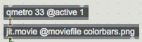
The jit.movie object is preloaded with an image of color bars. Video data is being sent out to a jit.pwindow as a matrix. We’re also sending that same matrix to a jit.unpack object, a jit.matrix object, and a print object.
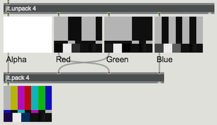
Video in jitter is composed of a 4-plane matrix - each of the four individual plane contains data on Alpha, Red, Green and Blue values, in that order. The jit.unpack object breaks this apart and displays each plane separately as a grayscale image. (The argument to jit.unpack determines the number of outputs that the object will have). Brighter pixels indicate higher intensity of the corresponding color. If you aren’t familiar with additive color (RGB), it can seem unintuitive - it reflects how colors of light behave in the real world rather than how colors are mixed using pigments.
Once we have unpacked our matrix, we are free to manipulate the individual planes in any way we want. In this case, we are swapping the red and green planes before we recombine them using the jit.pack object (as with jit.unpack, the argument to jit.pack determines the number of inlets/planes that the object will have).
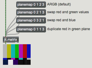
On the right side of the patch, we use the message to a jit.matrix to achieve the same result. When the jit.matrix object receives a message, it automatically fills with the values of the incoming matrix. The message determines the order in which the data from the incoming matrix is used to fill the planes of the jit.matrix. Click on the various maps to see how they affect the image. The default is , and tells the matrix to use plane 0 (alpha) from the incoming matrix as plane 0, 1 (red) as 1 and so on, resulting in an unaltered image. Switching the order of these planes, however, allows you to quickly substitute the values of one plane for another (i.e., ) or even one for multiple (i.e., ).
Instead of outputting an enormous list of values for every pixel (cell) in a matrix, jitter objects communicate using the message. Look at the print object below the jit.movie and note that the message sent out by our movie object is followed by some numbers and letters. This message acts as an alias to the data contained in a matrix. You can also explicitly set the name of a jit.matrix using and argument (e.g. jit.matrix mydata) and access that data anywhere in a patch (for an in-depth discussion of matrix data, read the document).
The jit.matrix object
Video media automatically sets the state of all four planes of a matrix based on the data contained in the current video frame, but sometimes we will want to work with matrix data without using pre-recorded media. The jit.matrix object provides us with a blank slate to create whatever type of matrix we want.
The next section shows how we can set the value of any point in a matrix using the message or all values at once using the message.
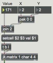
In the example on the left, jit.matrix 1 char 4 4 creates a one-plane matrix containing 16 pixels (4 rows and 4 columns).
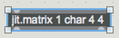
The fact that the matrix has only one plane means it uses only one value per cell - creating a grayscale image. The value is char data - integer values from 0-255, where 0 is solid black and 255 is solid white. Each pixel or cell in our matrix is addressed using x and y Cartesian coordinates, where the top left pixel is represented as cell 0 0. To manipulate your matrix, select x and y cells from 0-3 and then adjust the value. This composes a message in the format .
Note that setting the contents of the matrix does not output the matrix. It is only output when it receives a message which we create here by using the trigger object.
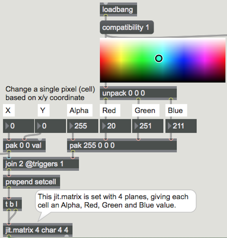
The right-hand example uses a 4-plane matrix that lets us to set ARGB (alpha, red, green, blue) data such as we find in video pixels. A swatch object (whose compatibility attribute is set to 1, which means that the object outputs integers between 0 - 255 istead of float values from 0. - 1.) is used to quickly set the RGB values.
Displaying the contents of a matrix
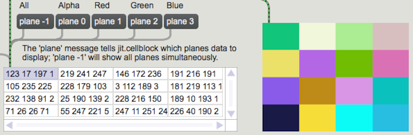
The jit.cellblock object gives us a way to view the contents of our jit.matrix object. Notice that as you manipulate the values in your matrix, the changes are reflected in the cellblock display. When using multi-plane matrices with the jit.cellblock object, the message allows you to specify which plane you are viewing the contents of. Sending a negative integer as the value allows you to see all at once.
The jit.print object will print the incoming matrix values to the Max console, one row per line.
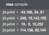
Keep in mind that for many matrices, this is a lot of data for either jit.print or jit.cellblock. A full HD 1920x1080 video matrix would print 1080 lines with 1920 columns. At 4 values per cell, that's 8,294,400 values per frame! In many cases, viewing the data with a jit.pwindow is the quickest way to get a sense of the data.