Examples
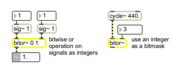
Bitwise or-operation of floating point signals
| Name | Type | Opt | Description |
|---|---|---|---|
| bitmask | int | opt | Sets the bitmask to be used by the bitor~ object. The default is . An integer value can be used as a bitmask regardless of the mode; the binary representation of this integer is the bitmask. |
| operational-mode (0 through 3) | int | opt | Specifies whether the floating-point signal or floating-point values will be processed as raw 32-bit floating-point values or converted to integer values for the bitwise operation. The modes of operation are: 0: Treat both floating-point signal inputs as raw 32-bit values (default). 1: Convert both floating-point signal inputs to integer values. 2: Treat the floating-point signal in the left inlet as a raw 32-bit value and treat the value in the right inlet as an integer. 3: Convert the floating-point signal in the left inlet to an integer and treat the right input as a raw 32-bit value. Note: If you convert the floating-point signal input to an integer and then convert it back, the resulting floating-point value will retain only 24 bits of integer resolution. |
| int | bitmask [int] |
In right inlet: An integer value can be used as a bitmask when supplied to the right inlet of the bitor~ object, provided that the proper mode is set. |
| float | bitmask [float] |
Performs the same function as . |
| bits | bitmask (32 ones or zeros) [list] |
In left inlet: The word , followed by a list containing 32 ones or zeros, specifies a bitmask to be used by bitor~. Alternately, a bitmask value can be set by using an int value in the right inlet. |
| mode | operational-mode (0 through 3) [int] |
In left inlet: The word , followed by a zero or one, specifies whether the floating signal or floating-point values will be processed as a raw 32-bit floating-point value or converted to an integer value for the bitwise operation. The modes of operation are: Mode Descriptions: 0 - Treat both floating-point signal inputs as raw 32-bit values (default). 1 - Convert both floating-point signal inputs to integer values. 2 - Treat the floating-point signal in the left inlet as a raw 32-bit value and treat the value in the right inlet as an integer. 3 - Convert the floating-point signal in the left inlet to an integer and treat the right input as a raw 32-bit value. Note: If you convert the floating-point signal input to an integer and then convert it back, the resulting floating-point value will retain only 24 bits of integer resolution. |
| signal | In left inlet: The floating-point signal is compared, in binary form, with the floating-point signal in the right inlet. The signal can be treated as either a floating-point signal or as an integer. In right inlet: The floating-point signal to be compared with the signal in the left inlet. The signal can be treated as either a floating-point signal or as an integer. The raw floating-point signal bit values are expressed in the following form: <1 sign bit> <8 exponent bits> <23 mantissa bits> |