Examples
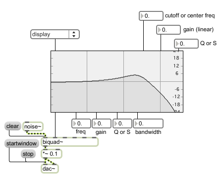
The filtergraph~ object greatly simplifies working with the biquad~ object
Graphical filter editor
| bang | In left inlet: In display mode, causes the filtergraph~ object to send its internally-stored biquad coefficients out the leftmost outlet. In the interactive filter modes, additionally causes the current filter parameters to be sent out their respective outlets (see Output). | |
| int | filter-parameter [int] |
Converted to . |
| float | filter-parameter [float] |
In 1st-5th inlets: When in display mode, a float in one of the first five inlets changes the current value of the corresponding biquad~ filter coefficient (a0, a1, a2, b1, and b2, respectively), recalculates the filter's frequency response based on these coefficients and causes a list of the current filter coefficients to be output from the leftmost outlet. In 6th inlet: Sets the center or cutoff frequency parameter for the filter and causes output. In 7th inlet: Sets the gain parameter for the filter and causes output. In 8th inlet: Sets the Q (resonance) or S (slope) parameter for the filter and causes output. Note: Input to any one of the inlets will recalculate the current filter's graph and trigger the output. |
| list | filter-parameters [list] |
In left inlet: A list of five float values which correspond to biquad~ filter coefficients sets the filtergraph~ object's internal values for these coefficients and causes the object to output the list out its left outlet. If filtergraph~ is in display mode, it will display the frequency response of the filter obtained from these coefficients. If more than five values are sent, they are interpreted as sets of cascaded biquad coefficients (see the message). in 6th inlet: A list of three values which correspond to center/cutoff frequency, gain and Q/S (resonance/slope), sets these values, recalculates the new filter coefficients and causes output. This is equivalent to the message. |
| anything | messages [list] |
Allows for backwards compatibility with obsolete messages: , , , , , , , , , , , , , , , , , and . |
| bandpass | filter-type [list] |
In left inlet: The word sets the filter type of the filtergraph~ object to bandpass mode. It is equivalent to the message. The frequency response of the filter is based on three parameters: cf (center frequency) gain, and Q (resonance). |
| bandstop | filter-type [list] |
In left inlet: The word sets the filter type of the filtergraph~ object to bandstop mode. It is equivalent to the message. The frequency response of the filter is based on three parameters: cf (center frequency) gain, and Q (resonance). |
| allpass | filter-type [list] |
In left inlet: The word sets the filter type of the filtergraph~ object to allpass mode.It is equivalent to the message. The frequency response of the filter is based on three parameters: cf (center frequency, or cutoff frequency) gain, and Q (resonance), although only the gain parameter has an effect on the amplitude response. An allpass filter is designed to modify the phase response (use the message to view the phase response). |
| analog | analog-filter-prototype-flag (0 or 1) [list] |
In left inlet: The word , followed by a or , toggles the analog filter prototype parameter for the bandpass, and peaknotch filters. Unlike the standard digital versions, these "imitation analog" filters do not have a notch at the nyquist frequency, and thus imitate the response of a analog filter. The imitation analog filters are slightly more computationally expensive, so this option is set to 0 (disabled) by default. |
| display | filter-type [list] |
In left inlet: The word sets the filter type of the filtergraph~ object to display only. It is equivalent to the message. In display mode, filtergraph~ simply displays the frequency response for a set of five biquad~ filter coefficients. |
| displaydot | mousable-bandwidth-display-flag (0 or 1) [list] |
In left inlet: The message, followed by a or , toggles the display of the mousable bandwidth region when filtergraph~ is in display mode. This allows you to use filtergraph~ as an interface to design and display your own filter algorithms. The default is disabled (by default, display mode functions uniquely as a display). |
| cascade | filter-coefficients (up to 24 groups of 5 floats) [list] |
In left inlet: The message works in display mode only. The word , followed by up to 24 groups of five float values corresponding to filter coefficients, will display a composite filter response which shows the multiplication of a group of biquad filters in cascade. |
| constraints | filter-index and minimum/maximum-constraint-pairs for frequency gain and Q(1 int and 6 floats) [list] |
In left inlet: The word , followed by seven numbers, allows you to constrain the frequency, amplitude and Q values within the specified ranges. This is useful to constrain values obtained by clicking and dragging. The first number should be an integer, and it specified the filter number whose constraints will be set. The remaining six numbers are floating-point values which set the minimum and maximum frequency values, the minimum and maximum amplitude values, and the minimum and maximum Q values, respectively. Specifying constraint values of zero will remove the constraints for that value. The message causes the filter coefficients to be output. |
| highpass | filter-type [list] |
In left inlet: The word sets the filter type of the filtergraph~ object to highpass mode.It is equivalent to the message. The frequency response of the filter is based on three parameters: cf (cutoff frequency) gain, and Q (resonance) or S (slope - used for the shelving filters). |
| highorder | a/b-grouped-filter-coefficients [list] |
The message works in display mode only. The word , followed by a list of n groups of biquad filter "a" coefficients and n-1 groups of biquad filter "b" coefficients, will display the response of an nth order filter. |
| highshelf | filter-type [list] |
In left inlet: The word sets the filter type of the filtergraph~ object to highshelf mode.It is equivalent to the message. The frequency response of the filter is based on three parameters: cf (cutoff frequency) gain, and S (slope). |
| gainmode | gain-parameter-flag (0 or 1) [list] |
In left inlet: The word , followed by a or , toggles the gain parameter for the lowpass, highpass, bandpass, and bandstop filters. The traditional definitions of these filters have a fixed gain of 1.0, but by gain-enabling them, their amplitude response can be scaled without the additional use of a signal multiply at the filters output.The default is 0 (disabled). |
| markers | frequency-value-display-markers (up to 64 frequencies) [list] |
In left inlet: The word , followed by a list of up to 64 frequency values will place visual markers (vertical lines) at these frequencies behind the graph. The message will set the markers used for both linear and logarithmic frequency displays. |
| mode | filter-type [list] |
In left inlet: The word , followed by a number from 0-9, sets the current filter type. The numbers and associated filter types are. Number - Filter type 0 - display only 1 - lowpass 2 - highpass 3 - bandpass 4 - bandstop 5 - peaknotch 6 - lowshelf 7 - highshelf 8 - resonant 9 - allpass In display mode, filtergraph~ displays the frequency response for a set of five biquad~ filter coefficients. In the other modes, it graphs the frequency response of a filter based on three parameters: cf (center frequency, or cutoff frequency) gain, and Q (resonance) or S (slope - used for the shelving filters). |
| (mouse) | You can change the filter parameters by clicking and dragging on the filtergraph~ object's display. By default, horizontal mouse dragging is mapped to cutoff frequency, and vertical mouse movement is mapped to gain (if is enabled). If the cursor is located directly over the edge of a filter band, however, the band rectangle is highlighted, indicating that clicking and dragging will map x-axis movement to adjust filter bandwidth instead of cutoff frequency. . If multiple bandwidth regions are overlapping, you can cycle through them by double-clicking on the topmost one. This is useful for accessing smaller bandwidth regions that might be otherwise "covered" by a larger region. |
|
| mousemode | mouse-x/y-axes-response-flags (2 ints) [list] |
In left inlet: The word followed by two int arguments, specifies the interpretation of horizontal and vertical mouse movement. With one argument, only the horizontal mouse mode is affected. The mouse mode values are the same for both axes: ( = off, = normal, = alternate). For horizontal movement (specified by the first argument), normal behavior means that clicking on the filter band and dragging horizontally changes the filter's cutoff frequency. When set to the alternate mouse mode (2), horizontal movement affects Q, or resonance. When turned off (0), mouse activity along the x-axis has no effect. For vertical movement (specified by the second argument), normal behavior means that the y-axis is mapped to gain during clicking and dragging activity. When the alternate mouse mode (2) is selected, vertical movement changes the Q (resonance) setting instead. When turned off (0), vertical mouse movement has no effect. |
| lowpass | filter-type [list] |
In left inlet: The word sets the filter type of the filtergraph~ object to lowpass mode.It is equivalent to the message. The frequency response of the filter is based on three parameters: cf (center frequency, or cutoff frequency) gain, and Q (resonance). |
| lowshelf | filter-type [list] |
In left inlet: The word sets the filter type of the filtergraph~ object to lowshelf mode.It is equivalent to the message. The frequency response of the filter is based on three parameters: cf (center frequency, or cutoff frequency) gain, and S (slope). |
| peaknotch | filter-type [list] |
In left inlet: The word sets the filter type of the filtergraph~ object to peaknotch mode.It is equivalent to the message. The frequency response of the filter is based on three parameters: cf (center frequency, or cutoff frequency) gain, and Q (resonance). |
| options | filter-specific (5 integers) [list] |
In left inlet: The word , followed by five integers, allows you to set the filter-specific options for a given filter. The first number specifies the filter whose options will be set. The remaining four integers set the filter mode ( message) gain-enabling flag ( message), analog filter prototype flag ( message) and interactive filter mode flag ( message), respectively. The message causes the filter coefficients to be re-evaluated and output. |
| params | filter-index frequency gain and Q [list] |
In left inlet: The word , when followed by three numbers specifying frequency, gain and Q, sets the filter parameters for the currently selected filter and triggers output. When followed by four numbers specifying filter number, frequency, gain and Q, this messages sets the filter parameters for the filter indicated and causes output. |
| query | frequency (Hz/cycles-per-second) [float] |
In left inlet: The word , followed by a float value, will cause the amplitude and phase response of the graph at that frequency to be sent out the sixth outlet of the filtergraph~ object as a list. |
| selectfilt | filter-index [int] |
Selects a specific filter as the one actively being edited and highlighted in the display. |
| set | filter-parameters [list] |
In left inlet: The word , followed by a list of five int values which correspond to biquad~ filter coefficients, sets the filtergraph~ object's internal values for these coefficients but does not cause output. If filtergraph~ is in display mode, it will display the frequency response of the filter obtained from these coefficients. in 6th inlet: A list of three values which correspond respectively to center/cutoff frequency, gain and Q/S (resonance/slope), sets these values, recalculates the new filter coefficients but does not cause output. In display mode this message has no effect. |
| resonant | filter-type [list] |
In left inlet: The word sets the filter type of the filtergraph~ object to resonant mode (resonant bandpass filter). It is equivalent to the message. The frequency response of the filter is based on three parameters: cf (center frequency) gain, and Q (resonance). |
| setconstraints | filter-index and minimum/maximum-constraint-pairs for frequency gain and Q(1 int and 6 floats) [list] |
In left inlet: The word , followed by seven numbers, allows you to set the frequency, amplitude and Q constraint values within the specified ranges without causing output. This is useful to constrain values obtained by clicking and dragging. The first number should be an integer, and it specified the filter number whose constraints will be set. The remaining six numbers are floating-point values which set the minimum frequency, maximum frequency, minimum amplitude, maximum amplitude, minimum Q and maximum Q, respectively. Specifying constraint values of zero will remove the constraints for that value. |
| setfilter | filter number [list] |
In left inlet: The word , followed by a number, specifies the filter, by number, which is the currently selected filter in a multiple filter array. Filters are numbered from 1. |
| setoptions | filter-specific (5 integers) [list] |
In left inlet: The word , followed by five integers, allows you to set the filter-specific options for a given filter without triggering output. The first number specifies the filter whose options will be set (filters are numbered from 1). The remaining four integers set the filter mode ( message) gain-enabling flag ( message), analog filter prototype flag ( message) and interactive filter mode flag ( message), respectively. |
| setparams | filter-index frequency gain and Q [list] |
In left inlet: The word , when followed by three numbers specifying frequency, gain and Q, sets the filter parameters for the currently selected filter without triggering output. When followed by four numbers specifying filter number, frequency, gain and Q, this messages sets the filter parameters for the filter indicated, without triggering output. |
| whichfilt | filter-index [int] |
Selects a specific filter as the one actively being edited (without highlighting it in the display). |
| Name | Type | g/s | Description |
|---|---|---|---|
| autoout | int def.:0 |
Toggles the automatic output on load feature. tells filtergraph~ to automatically output its coefficients and parameters when a patch is loaded. filtergraph~ saves its current state in a patcher. disables this feature. The default value is 1 (enabled). The filtergraph~ object will respond to a message sent to it when a patcher is loaded. |
|
| bgcolor | float | Sets the color of the filtergraph~ object background (i.e., the area above the filter curve) in RGBA format. | |
| bordercolor | float | Sets the color of the rectangle that outlines the filtergraph~ object display in RGBA format. | |
| bwidthcolor | float | Sets the color of the bandwidth rectangle (and unselected tint within that rectangle) in RGBA format. | |
| curvecolor | float | Sets the color of the filtergraph~ object's curve line (i.e., the line that separated the areas above and below the filter curve) in RGBA format. | |
| dbdisplay | int def.:1 |
Toggles the display of numerical values for gain change in deciBels represented by the small ticks at the right-hand side of the object's display | |
| domain | float def.:20. 20000. |
When followed by a list of two integers that specify frequencies in Hz, changes the frequency display range of the object. The default display range is from 0 Hz to half the sampling rate (the Nyquist frequency). | |
| edit_Q | float | Sets the Q of the currently selected filter. For single filters, the filter type displayed by the filtergraph~ object is the currently selected filter; when dealing with multiple filters, the currently selected filter is set using the message (with the filters being numbered from 1). |
|
| edit_amp | float | Sets the amplitude of the currently selected filter. For single filters, the filter type displayed by the filtergraph~ object is the currently selected filter; when dealing with multiple filters, the currently selected filter is set using the message (with the filters being numbered from 1). |
|
| edit_analog | int | Toggles the analog filter prototype parameter for the currently selected filter when filtergraph~ is in bandpass or peaknotch mode. For more information on analog filter mode, see the message listing above. For single filters, the filter type displayed by the filtergraph~ object is the currently selected filter; when dealing with multiple filters, the currently selected filter is set using the message (with the filters being numbered from 1). |
|
| edit_displaydot | int | Toggles the display of the mousable bandwidth region for the currently selected filter when filtergraph~ is in display mode. For more information, see the message listing above. For single filters, the filter type displayed by the filtergraph~ object is the currently selected filter; when dealing with multiple filters, the currently selected filter is set using the message (with the filters being numbered from 1). |
|
| edit_filter | int def.:0 |
Selects the currently selected filter by number. Filters are numbered from 1. | |
| edit_freq | float | Sets the center/cutoff frequency of the currently selected filter. For single filters, the filter type displayed by the filtergraph~ object is the currently selected filter; when dealing with multiple filters, the currently selected filter is set using the message (with the filters being numbered from 1). |
|
| edit_gainmode | int | Toggles the gain parameter for the currently selected filter if it is in lowpass, highpass, bandpass, or bandstop filter mode. For more information, see the message listing above. For single filters, the filter type displayed by the filtergraph~ object is the currently selected filter; when dealing with multiple filters, the currently selected filter is set using the message (with the filters being numbered from 1). |
|
| edit_maxQ | atom | Sets the maximum Q value of the currently selected filter. For single filters, the filter type displayed by the filtergraph~ object is the currently selected filter; when dealing with multiple filters, the currently selected filter is set using the message (with the filters being numbered from 1). |
|
| edit_maxamp | atom | Sets the maximum amplitude of the currently selected filter. For single filters, the filter type displayed by the filtergraph~ object is the currently selected filter; when dealing with multiple filters, the currently selected filter is set using the message (with the filters being numbered from 1). |
|
| edit_maxfreq | atom | Sets the upper bound for the frequency of the currently selected filter. For single filters, the filter type displayed by the filtergraph~ object is the currently selected filter; when dealing with multiple filters, the currently selected filter is set using the message (with the filters being numbered from 1). |
|
| edit_minQ | atom | Sets the minimimum Q value of the currently selected filter. For single filters, the filter type displayed by the filtergraph~ object is the currently selected filter; when dealing with multiple filters, the currently selected filter is set using the message (with the filters being numbered from 1). |
|
| edit_minamp | atom | Sets the minimimum amplitude of the currently selected filter. For single filters, the filter type displayed by the filtergraph~ object is the currently selected filter; when dealing with multiple filters, the currently selected filter is set using the message (with the filters being numbered from 1). |
|
| edit_minfreq | atom | Sets the minimimum frequency of the currently selected filter. For single filters, the filter type displayed by the filtergraph~ object is the currently selected filter; when dealing with multiple filters, the currently selected filter is set using the message (with the filters being numbered from 1). |
|
| edit_mode | int | Sets the filter type for the currently selected filter. The available options are: display lowpass highpass bandpass bandstop peaknotch lowshelf highshelf resonant allpass For single filters, the filter type displayed by the filtergraph~ object is the currently selected filter; when dealing with multiple filters, the currently selected filter is set using the message (with the filters being numbered from 1). |
|
| fgcolor | float | Sets the color of the filtergraph~ object foreground (i.e., the area below the filter curve) in RGBA format. | |
| fullspect | int def.:0 |
Selects half-spectrum or full-spectrum display. (the default) specifies a half-spectrum from 0 Hz to the Nyquist frequency (half the sampling rate). specifies a full (mirrored) spectrum from -Nyquist to +Nyquist (the spectrum is mirrored around 0 Hz). In full spectrum mode, the display has a red marker at DC(0 Hz). |
|
| hbwidthcolor | float | Sets the tint of the interior of the bandwidth rectangle when it is selected in RGBA format. | |
| hcurvecolor | float | Sets the color of the filter curve for an individual filter that is highlighted by moving the cursor over it. The color is specific, naturally, in RGBA format. | |
| linmarkers | float def.:5512.5 11025. 16537.5 |
When followed by a list of up to 64 int values, will set markers for the linear frequency display (See the markers message). By default, the markers are set at ± SampleRate/4, SampleRate/2, and (3 * SampleRate)/4. | |
| logamp | int def.:1 |
Sets the amplitude display scale. sets a linear amplitude display. sets a log display scale (default). |
|
| logfreq | int def.:1 |
Sets the frequency display scale. sets a linear frequency display. sets a log display scale (default). |
|
| logmarkers | float def.:10. 100. 1000. 10000. |
When followed by a list of up to 64 int values, will set markers for the log frequency display (See the markers message). By default, the markers are set at± 50Hz, 500Hz and 5kHz at 44.1kHz. These values correspond to ± 0.007124, 0.071238, and 0.712379 radians for any sample rate. | |
| markercolor | float | Sets the color of the filtergraph~ display markers in RGBA format. | |
| nfilters | int def.:1 |
Sets the number of cascaded biquad filters displayed in the filtergraph. The range is between 1 and 24. When using more than one filter, the output of the filtergraph~ should be sent to a cascade~ object instead of a biquad~. | |
| numdisplay | int def.:1 |
Toggles the display of numerical values for frequency, gain and Q values while clicking and dragging the bandwidth rectangle with the mouse. | |
| phasespect | int def.:0 |
Specifies whether to display the amplitude or phase, with respect to frequency. sets a frequency-amplitude display (default), and sets a frequencyphase display. | |
| range | float def.:0.0625 16. |
Sets the amplitude display range of object. The amplitude is displayed from 0 to the range value along the vertical axis of the graph. (default value 2.0) | |
| textcolor | float | Sets the color of the filtergraph~ object text in RGBA format. |
| Name | Description |
|---|---|
| Color | Choosing the Color... menu item from the Object menu when the object is selected opens a color picker, permitting adjustment to the appearance of the filtergraph~ object. |
| Name | Description |
|---|---|
| allpass~ | Allpass filter |
| biquad~ | Two-pole, two-zero filter |
| cascade~ | Cascaded series of biquad filters |
| delay~ | Delay line specified in samples or Max tempo-relative time format |
| filtercoeff~ | Signal-rate filter coefficient generator |
| lores~ | Resonant lowpass filter |
| reson~ | Resonant bandpass filter |
| teeth~ | Comb filter with feedforward and feedback delay control |
| zplane~ | Graph filter poles and zeros on the Z-plane |