Description
Use the filtergraph~ object to generate filter coefficients for the biquad~ or cascade~ objects with a graphical interface.
Examples
Discussion
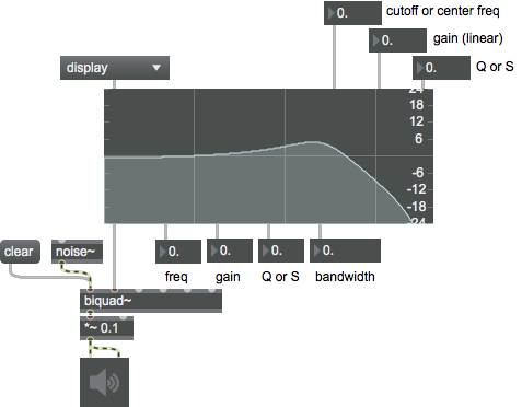
The horizontal axis of the filtergraph~ object's display represents frequency and the vertical axis represents amplitude. The curve displayed reflects the frequency response of the current filter model. The frequency response is the amount that the filter amplifies or attenuates the frequencies present in an audio signal. The biquad~ (or cascade~) objects do the actual filtering based on the coefficients that filtergraph~ provides.
The cutoff frequency (or center frequency) is the focal frequency of a given filter's activity. Its specific meaning is different for each filter type, but it can generally be identified as a transitional point (or center of a peak/trough) in the graph's amplitude curve. It is marked in the display by a colored rectangle whose width corresponds to the bandwidth of the filter.
The bandwidth (the transitional band in Hz) is the principal range of a filter's effect, centered on the cutoff frequency. The edges of a filter's bandwidth are located where the frequency response has a 3dB change in amplitude from the cutoff or center frequency. Q (also known as resonance) describes filter "width" as the ratio of the center/cutoff frequency to the bandwidth. Using Q instead of bandwidth lets us move the center/cutoff frequency while keeping a constant bandwidth across octaves. The Q parameter for shelving filters is often called S (or slope), although it is ostensibly the same as Q.
The filter's gain is the linear amplitude at the center or cutoff frequency. The interpretation of the gain parameter depends somewhat on the type of filter. The gain may also affect a shelf or large region of the filter's response.
Arguments
None.
Attributes
autoout [int] (default: 0)
Toggles the output of coefficients on load.
bgcolor [4 floats]
Sets the background color in RGBA format.
curvecolor [4 floats]
Sets the curve color in RGBA format. The attribute is mapped to the style color.
dbdisplay [int] (default: 1)
Toggles db gain value display.
display_flat [int] (default: 1)
Toggles flat sign display.
domain [2 floats] (default: 20. 20000.)
Sets frequency display span.
edit_Q [float]
Sets the bandwidth (Q) for the currently selected filter.
edit_amp [float]
Sets the amplitude for the currently selected filter.
edit_analog [int]
Toggles the analog filter prototype parameter for the currently selected filter when filtergraph~ is in bandpass or peaknotch mode. For more information on analog filter mode, see the message listing above.
For single filters, the filter type displayed by the filtergraph~ object is the currently selected filter; when dealing with multiple filters, the currently selected filter is set using the message (with the filters being numbered from 0).
edit_displaydot [int]
Toggles the display of the mousable bandwidth region for the currently selected filter when filtergraph~ is in display mode. For more information, see the message listing above.
For single filters, the filter type displayed by the filtergraph~ object is the currently selected filter; when dealing with multiple filters, the currently selected filter is set using the message (with the filters being numbered from 0).
edit_filter [int] (default: 0)
Selects which filter to edit if nfilters is greater than 1. Filters are numbered from 0.
Possible values:
'0'
edit_freq [float]
Sets center/cutoff frequency for the currently selected filter.
edit_gainmode [int]
Tggles the gain parameter for the currently selected filter.
edit_maxQ [atom]
Sets the maximum Q of the currently selected filter.
edit_maxamp [atom]
Sets the maximum amplitude for the currently selected filter.
edit_maxfreq [atom]
Sets the upper bound for the frequency of the currently selected filter.
edit_minQ [atom]
Sets the minimum bandwidth (Q) for the currently selected filter.
edit_minamp [atom]
Sets the minimum amplitude for the currently selected filter.
edit_minfreq [atom]
Sets the minimum frequency for the currently selected filter.
edit_mode [int]
Sets the response shape for the currently selected filter.
Possible values:
0 = 'display'
(
None/arbitrary
)
1 = 'lowpass'
(
Low frequencies pass, high frequencies attenuated
)
2 = 'highpass'
(
High frequencies pass, low frequencies attenuated
)
3 = 'bandpass'
(
A band of frequencies pass, everything else is attenuated
)
4 = 'bandstop'
(
A band of frequencies are attenuated, everything else passes
)
5 = 'peaknotch'
(
A band of frequencies is attenuated or boosted depending on the gain
)
6 = 'lowshelf'
(
Low frequencies are attenuated or boosted depending on the gain
)
7 = 'highshelf'
(
High frequencies are attenuated or boosted depending on the gain
)
8 = 'resonant'
(
Another bandpass filter
)
9 = 'allpass'
(
All frequencies pass through but the phase is affected
)
fullspect [int] (default: 0)
Display the full frequency spectrum from -Nyquist to +Nyquist.
hcurvecolor [4 floats]
Sets the selection color in RGBA format. The attribute is mapped to the style color.
linmarkers [16 floats] (default: 5512.5 11025. 16537.5)
Marker positions for the linear frequency display. By default, the markers are set at ± SampleRate/4, SampleRate/2, and (3 * SampleRate)/4.
logamp [int] (default: 1)
Sets the amplitude display mode.
Possible values:
0 = 'Linear'
(
Linear amplitude display
)
Displays amplitudes using a linear scale.
1 = 'Logarithmic'
(
Log amplitude display
)
Displays amplitudes using a logarithmic scale.
logfreq [int] (default: 1)
Sets the frequency display mode.
Possible values:
0 = 'Linear'
(
Linear frequency display
)
Displays frequencies using a linear scale.
1 = 'Logarithmic'
(
Log frequency display
)
Displays frequencies using a logarithmic scale.
logmarkers [16 floats] (default: 10. 100. 1000. 10000.)
Marker positions for the log frequency display. By default, the markers are set at± 50Hz, 500Hz and 5kHz at 44.1kHz. These values correspond to ± 0.007124, 0.071238, and 0.712379 radians for any sample rate.
markercolor [4 floats]
Sets the grid color in RGBA format. The attribute is mapped to the style color.
nfilters [int] (default: 1)
Number of cascaded biquad filters displayed. The range is between 1 and 24. When using more than one filter, the output of the filtergraph~ should be sent to a cascade~ object instead of a biquad~.
numdisplay [int] (default: 1)
Toggles numerical value display.
parameter_enable [int]
Enables use of this object with Max for Live Parameters and allows for setting initial parameter values in the Max environment.
phasespect [int] (default: 0)
Toggles phase response display.
range [2 floats] (default: 0.0625 16.)
Sets the amplitude display range.
style [symbol]7.0.0
Sets the style to be applied to the object. Styles can be set using the Format palette.
textcolor [4 floats]
Sets the color of the labels in RGBA format. The attribute is mapped to the style color.
Common Box Attributes
annotation [symbol]
Sets the text that will be displayed in the Clue window when the user moves the mouse over the object.
background [int] (default: 0)
Adds or removes the object from the patcher's background layer. adds the object to the background layer, removes it. Objects in the background layer are shown behind all objects in the default foreground layer.
color [4 floats]
Sets the color for the object box outline.
fontface [int]
Sets the type style used by the object. The options are:
plain
bold
italic
bold italic
Possible values:
0 = 'regular'
1 = 'bold'
2 = 'italic'
3 = 'bold italic'
fontname [symbol]
Sets the object's font.
fontsize [float]
Sets the object's font size (in points).
Possible values:
'8'
'9'
'10'
'11'
'12'
'13'
'14'
'16'
'18'
'20'
'24'
'30'
'36'
'48'
'64'
'72'
hidden [int] (default: 0)
Toggles whether an object is hidden when the patcher is locked.
hint [symbol]
Sets the text that will be displayed in as a pop-up hint when the user moves the mouse over the object in a locked patcher.
ignoreclick [int] (default: 0)
Toggles whether an object ignores mouse clicks in a locked patcher.
patching_rect [4 floats] (default: 0. 0. 100. 0.)
Sets the position and size of the object in the patcher window.
position [2 floats]
Sets the object's x and y position in both patching and presentation modes (if the object belongs to its patcher's presentation), leaving its size unchanged.
presentation [int] (default: 0)
Sets whether an object belongs to the patcher's presentation.
presentation_rect [4 floats] (default: 0. 0. 0. 0.)
Sets the x and y position and width and height of the object in the patcher's presentation, leaving its patching position unchanged.
rect [4 floats]
Sets the x and y position and width and height of the object in both patching and presentation modes (if the object belongs to its patcher's presentation).
size [2 floats]
Sets the object's width and height in both patching and presentation modes (if the object belongs to its patcher's presentation), leaving its position unchanged.
textcolor [float]
Sets the color for the object's text in RGBA format.
textjustification [int]
Text Justification
Possible values:
0 = 'left'
1 = 'center'
2 = 'right'
varname [symbol]
Sets the patcher's scripting name, which can be used to address the object by name in pattr, scripting messages to thispatcher, and the js object.
Parameter Attributes
Order
Sets the order of recall of this parameter. Lower numbers are recalled first. The order of recall of parameters with the same order number is undefined.
Parameter Mode Enable
Parameter Mode Enable (not available from Parameters window)
Link to Scripting Name
When checked, the Scripting Name is linked to the Long Name attribute.
Long Name
The long name of the parameter. This name must be unique per patcher hierarchy.
Short Name
Sets the short name for the object's visual display. The maximum length varies according to letter width, but is generally in a range of 5 to 7 characters.
Type
Specifies the data type. The data types used in Max for Live are:
Float
Int
Enum (enumerated list)
Blob
Note: By convention, the Live application uses floating point numbers for its calculations; the native integer representation is limited to a range of 0-255 (similar to the char data type used in Jitter). When working with Live UI objects whose integer values are likely to be outside of the 0-255 range, the Type attribute should be set to Float, and the Unit Style attribute should be set to Int.
Range/Enum
When used with an integer or floating point data type, this field is used to specify the minimum and maximum values of the parameter.
When used with an enumerated list (Enum) data type, this field contains a space-delimited list of the enumerated values (if list items contain a space or special characters, the name should be enclosed in double quotes).
Modulation Mode
Sets the Modulation Mode used by the Live application. The modulation modes are:
None
Unipolar
Bipolar
Additive
Absolute
Modulation Range
This parameter is only used with the Absolute modulation mode. It specifies defines the range of values used.
Initial Enable
When checked (set to 1), the UI object can store an initialization value. The value is set using the Initial attribute (see below).
Initial
Sets the initial value to be stored and used when the Initial Enable attribute is checked.
Unit Style
Sets the unit style to be used when displaying values. The unit style values are: Int: displays integer values
Float: displays floating point values
Time: displays time values in milliseconds (ms)
Hertz: displays frequency values (Hz/kHz).
deciBel: displays loudness (dB)
%: Percentage
Pan: displays Left and Right values
Semitones: displays steps (st)
MIDI: displays pitch corresponding to the MIDI note number
Custom: displays custom data type
Native: defaults to floating point values
Custom Units
Sets the units to be used with the 'Custom' unit style (see "Unit Style", above). Custom unit strings may be simple symbols (e.g. "Harmonic(s)"), in which case the parameter's value will be displayed in its 'Native' display mode, followed by the symbol (e.g. "12 Harmonic(s)" for an Int-typed parameter or "12.54 Harmonic(s)" for a Float-typed parameter). For additional control over the numerical component displayed, a sprintf-style string may be used (e.g. "%0.2f Bogon(s)", which would display a value such as ".87 Bogons").
Exponent
When set to a value other than 1., the parameter's input and output values will be exponentially scaled according to the factor entered in this column.
Steps
The number of steps available between the minimum and maximum values of a parameter. For instance, if the parameter has a range from 0.-64., with Steps set to 4, the user can only set the parameter to 0, 21.33, 42.66 and 64.
Parameter Visibility
For automatable parameters (Int, Float, Enum), 'Stored Only' disables automation, although parameter values are stored in presets. 'Hidden' causes the parameter's value to be ignored when storing and recalling data. Non-automatable parameters (Blob) are 'Stored Only' by default, and can be set to 'Hidden', if desired.
Update Limit (ms)
Speed limits values triggered by automation.
Defer Automation Output
Defers values triggered by automation.
Messages
bang
int
Arguments
In 1st-5th inlets: When in display mode, a float in one of the first five inlets changes the current value of the corresponding biquad~ filter coefficient (a0, a1, a2, b1, and b2, respectively), recalculates the filter's frequency response based on these coefficients and causes a list of the current filter coefficients to be output from the leftmost outlet.
In 6th inlet: Sets the center or cutoff frequency parameter for the filter and causes output.
In 7th inlet: Sets the gain parameter for the filter and causes output.
In 8th inlet: Sets the Q (resonance) or S (slope) parameter for the filter and causes output.
Note: Input to any one of the inlets will recalculate the current filter's graph and trigger the output.
float
Arguments
In 6th inlet: Sets the center or cutoff frequency parameter for the filter and causes output.
In 7th inlet: Sets the gain parameter for the filter and causes output.
In 8th inlet: Sets the Q (resonance) or S (slope) parameter for the filter and causes output.
Note: Input to any one of the inlets will recalculate the current filter's graph and trigger the output.
list
Arguments
a1 [float]
a2 [float]
b1 [float]
b2 [float]
in 6th inlet: A list of three values which correspond to center/cutoff frequency, gain and Q/S (resonance/slope), sets these values, recalculates the new filter coefficients and causes output. This is equivalent to the message.
anything
Arguments
bandpass
Arguments
gain [float]
Q [float]
bandstop
Arguments
gain [float]
Q [float]
allpass
Arguments
gain [float]
Q [float]
analog
Arguments
dictionary
Arguments
display
Arguments
displaydot
Arguments
cascade
Arguments
constraints
Arguments
minimum-frequency [float]
maximum-frequency [float]
minimum-gain [float]
maximum-gain [float]
minimum-Q [float]
maximum-Q [float]
flat
Arguments
Lowpass and highpass filters: Q values set to 0.707, and gain coefficients are set to 1. (0dB)
Band pass and band stop filters are ignored.
All other filter types: The gain coefficients are set to 1. (0dB)
highpass
Arguments
gain [float]
Q [float]
highorder
Arguments
highshelf
Arguments
gain [float]
slope [float]
gainmode
Arguments
markers
Arguments
mode
Arguments
Number - Filter type
0 - display only
1 - lowpass
2 - highpass
3 - bandpass
4 - bandstop
5 - peaknotch
6 - lowshelf
7 - highshelf
8 - resonant
9 - allpass
In display mode, filtergraph~ displays the frequency response for a set of five biquad~ filter coefficients. In the other modes, it graphs the frequency response of a filter based on three parameters: cf (center frequency, or cutoff frequency) gain, and Q (resonance) or S (slope - used for the shelving filters).
(mouse)
If multiple bandwidth regions are overlapping, you can cycle through them by double-clicking on the topmost one. This is useful for accessing smaller bandwidth regions that might be otherwise "covered" by a larger region.
mousemode
Arguments
y-response-flag [int]
For horizontal movement (specified by the first argument), normal behavior means that clicking on the filter band and dragging horizontally changes the filter's cutoff frequency. When set to the alternate mouse mode (2), horizontal movement affects Q, or resonance. When turned off (0), mouse activity along the x-axis has no effect.
For vertical movement (specified by the second argument), normal behavior means that the y-axis is mapped to gain during clicking and dragging activity. When the alternate mouse mode (2) is selected, vertical movement changes the Q (resonance) setting instead. When turned off (0), vertical mouse movement has no effect.
lowpass
Arguments
gain [float]
Q [float]
lowshelf
Arguments
gain [float]
slope [float]
peaknotch
Arguments
gain [float]
Q [float]
options
Arguments
filter-mode [int]
gain-enable-flag [int]
analog-filter-prototype-flag [int]
interactive-filter-mode-flag [int]
params
Arguments
frequency [float]
gain [float]
Q [float]
query
Arguments
selectfilt
Arguments
set
Arguments
a1/gain [float]
a2/Q [float]
b1 [float]
b2 [float]
in 6th inlet: A list of three values which correspond respectively to center/cutoff frequency, gain and Q/S (resonance/slope), sets these values, recalculates the new filter coefficients but does not cause output. In display mode this message has no effect.
resonant
Arguments
gain [float]
Q [float]
setconstraints
Arguments
minimum-frequency [float]
maximum-frequency [float]
minimum-gain [float]
maximum-gain [float]
minimum-Q [float]
maximum-Q [float]
setfilter
Arguments
setoptions
Arguments
filter-mode [int]
gain-enable-flag [int]
analog-filter-prototype-flag [int]
interactive-filter-mode-flag [int]
setparams
Arguments
frequency [float]
gain [float]
Q [float]
whichfilt
Arguments
Output
float
Out second through fifth outlets: Frequency, Gain (linear), Resonance (Q) and Bandwidth output in response to clicks on the filtergraph~ object.
int
Out rightmost (seventh) outlet: Filter number. Indicates which of the cascaded biquad filters is being highlighted and/or edited.
list
Out leftmost outlet: a list of 5 floating-point filter coefficients for the biquad~ object. Coefficients output in response to mouse clicks and changes in the coefficient or filter parameter inlets. They are also output when the audio is turned on, and optionally when the patch is loaded if the automatic output option is turned on (see message).
Out sixth outlet: a list of 2 floating-point values (amplitude, phase) output in response to the message (see above).
See Also
| Name | Description |
|---|---|
| Sound Processing Techniques | Sound Processing Techniques |
| allpass~ | Apply an allpass filter effect |
| biquad~ | Two-pole, two-zero filter |
| cascade~ | Cascaded series of biquad filters |
| delay~ | Delay a signal |
| filtercoeff~ | Signal-rate filter coefficient generator |
| lores~ | Resonant lowpass filter |
| reson~ | Resonant bandpass filter |
| teeth~ | Comb filter with feedforward and feedback delay control |
| zplane~ | Graph filter poles and zeros on the Z-plane |
| Audio Filtering | Audio Filtering |