In this tutorial, we'll look at the use of waveshaping to modify an input signal, simulating the distortion present in overdriven amplifiers. In the realm of analogue audio, all amplifiers introduce some form of distortion into the signal. The ability to creatively harness this by deliberately overdriving distortion circuits is difficult to simulate in a digital audio environment, as the natural artifacts and nonlinearities that render tube and transistor amplifier distortion so interesting are absent in the digital signal path. One way to overcome this is to simulate the distortion caused by amplifiers by using lookup tables to change the dynamic response of an input signal. Unlike the previous tutorials, which look at dynamics from a macro- (or envelope) perspective, this tutorial looks at sound amplitudes on a sample-by-sample basis.
A review of the tutorial that covers waveshaping synthesis may be useful to understand how the lookup~ object works in MSP.
Splitting bands
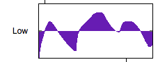
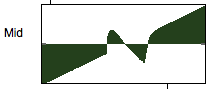
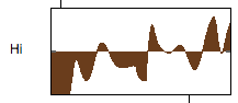
One of the attributes of cool-sounding distortion circuits is that they are frequency-dependent as well as amplitude-dependent in their behavior; that is to say, the way in which they shape an input signal depends not only on how loud the sound comes in, but also the frequency components in that sound. Some distortion circuits process high frequencies far more harshly than bass frequencies; some distort a narrow range of frequencies in the mid-range and leave high sounds relatively pure. In order to simulate this, we create an MSP signal chain that splits our input signal into three bands for low, medium, and high frequencies.
The state-variable (svf~ --- colored red) object in our patcher takes the output of our sample playback logic and applies four filters to the signal simultaneously: a lowpass filter (output from the left outlet), a highpass filter (output from the second outlet), a bandpass filter (output from the third outlet), and a bandreject or notch filter (output form the last outlet). We're only interested in the first three, which roughly correspond to the bass, middle, and treble of our input signal.
Applying distortion
A transfer function with multiple zero-crossing points will have the result of adding additional harmonics to any relatively periodic waveform. In amplifier distortion, this is an important component of the 'warm' effect of tube amplification.
Notice how the mid-range now has a harsh overdriven sound to it. What we've done in drawing that shape is introduce a set of additional zero-crossings around the normal zero point in the waveform. The result of this will be nonlinearities in the mid-range signal whenever its sample amplitude comes close to zero. This simulates the properties of many solid state transistor distortion circuits (such as guitar pedals), which 'kink' the signal at specific intervals to generate high harmonics from the signal.
This type of waveshape creates a harsh distortion similar to the way digital distortion effects work. By introducing noise (random activity) into the waveshape, we create the potential for completely arbitrary distortion effects that resemble less an amplifier circuit than a 'digital' effects process.
Resetting and smoothing
The MSP peek~ object, you may recall, allows us to programmatically fill buffer~ objects with samples according to patcher logic in Max. The uzi object, when it receives a , sets up a chain of events that fill the appropriate buffer~ object with an ascending ramp of values from to . When the lookup~ object uses this curve, the incoming signal gets passed unchanged.
The smoothing subpatches, which are triggered whenever you release the mouse from drawing in the waveform~ object, triggers an uzi object that takes each sample currently in the buffer~ and averages it with its previous sample, creating a smoother curve than would be possible by freehand drawing.
Summary
Waveshaping is an exciting synthesis technique that allows you to create complex timbres by running an oscillator through a lookup table; when used as a signal-processing technique with complex audio input, it can be used to simulate all manner of distortion effects. Because real-life amplifier distortion changes depending on the frequency content of the input signal, one way to simulate this distortion is to split an audio signal into several frequency bands and waveshape each one independently. While it's possible to scientifically measure and model the responses of different distortion circuits, freehand drawing in the waveform~ object allows us to experiment with different curves and hear them directly.