Global illumination
Let's keep working on our outdoor scene and see what still needs to be added. Now we have a bright light illuminating the scene, but if you turn the camera around, this is what the back of the cube looks like:
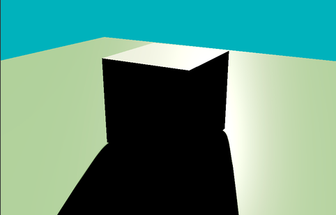
The cube casts a long black shadow that, once again, looks somewhat "unnatural." The image still doesn't "look quite right", and it's because we're not considering all of the lighting phenomena that contribute to the illumination of the scene. Before getting to the details, take a look at this comparison:
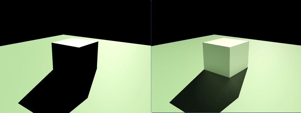
On the left, we have our scene as rendered right now; on the right, there's the same scene rendered, considering a more comprehensive range of lighting interactions. The image on the right looks undoubtedly more "plausible," but what are the missing lighting interactions? To give you a solid answer to this question, we have to go a step deeper into understanding how light interacts with physical objects and how to render such interactions on screen.
Surface-light interactions
When light illuminates a surface, various physical interactions occur between the light (electromagnetic radiation) and the material. These interactions determine how we perceive the surface's color, brightness, and overall appearance. Depending on the surface's properties, the light can be absorbed, reflected, refracted, or transmitted.

These surface-light interactions may coexist and depend on the properties of the material of which the surface is composed. For example, a black wall tends to absorb most of the light it receives, a window lets you see through it because it can transmit light, and a mirror reflects all the received light in the specular direction. The so-called BRDF (Bidirectional Reflectance Distribution Function) describes these complex light-surface interactions. A BRDF describes how light reflects off a surface, defining the relationship between incoming light (from a given direction) and outgoing reflected light (in another direction).

The object jit.gl.pbr (Physics-Based Render) uses BRDF functions to reproduce different materials' appearance under various lighting conditions. But if jit.gl.pbr is already accounting for generating plausible surface-light interactions, why doesn't our 3D scene look correct?
When a surface is illuminated, part of the light is reflected into the environment. The BRDF of the material describes how such reflections behave, but the amount of light emitted back into the scene should contribute to the illumination of other surfaces. jit.gl.pbr applies the correct light-surface response only for the light coming directly from the light source (direct illumination) but doesn't account for the amount of light coming from other objects' reflections (indirect illumination).
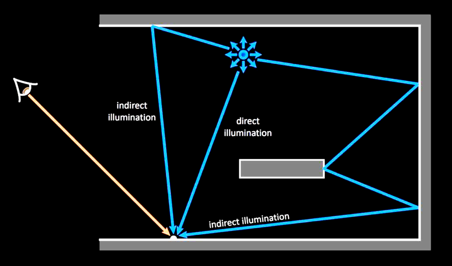
If you come from the audio realm, you can compare direct and indirect illumination to what happens when sound waves propagate in a room. The direct component is the sound coming directly from the sound source to the listener along the shortest possible path, while the indirect components are the sound waves reaching the listener after a certain number of bounces off the room's walls, floor, and ceiling.
In real-world lighting, direct and indirect illumination combine to produce the complex lighting effects we experience. If we compare again the two cubes side-by-side, we can see the impact of adding indirect illumination to the scene.

The light bouncing off the floor illuminates the faces of the cube not reached by direct illumination, and the light bouncing off the cube illuminates the shadowed floor.
Now, how can we compute direct and indirect illumination?
The Rendering Equation
In 1986, James Kajiya introduced a mathematical formulation used in computer graphics to describe how light interacts with surfaces to produce the color and brightness we perceive. This formulation goes under the name of the rendering equation:
Many possible formulations exist for the rendering equation, but for the sake of this article, I'll just focus on the version for non-translucent materials.
If we go beyond the initial aversion to Greek letters, we can break this function into pieces and discover that it's pretty simple and elegant.
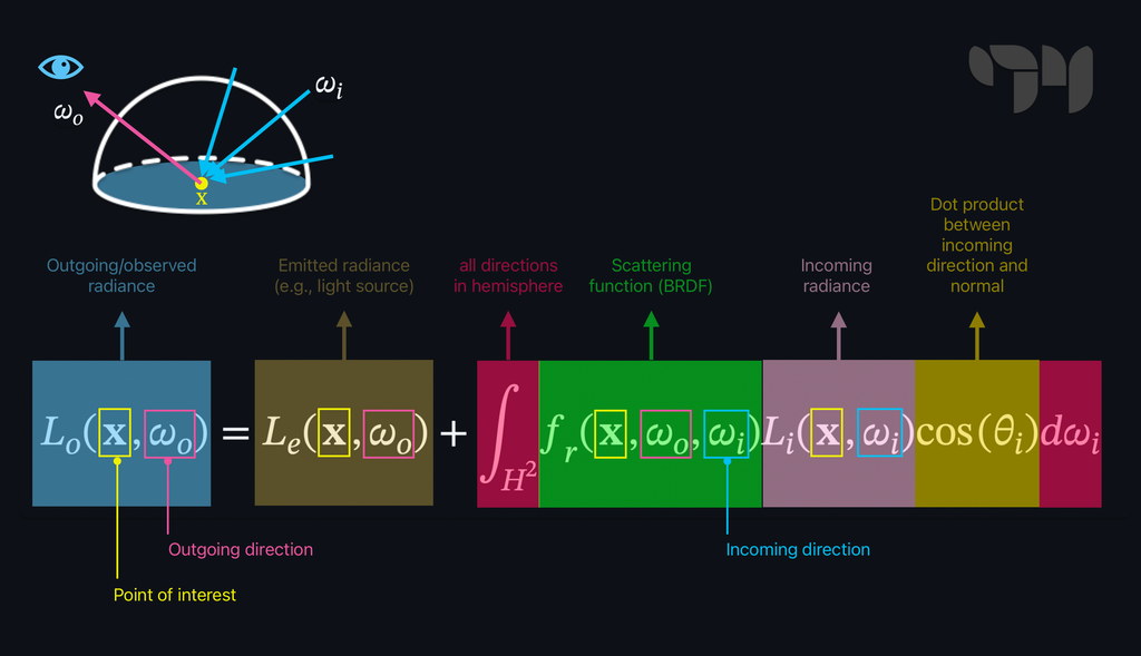
The rendering equation describes how much light is visible from a point on a surface looking in a specific direction . In other words, it can tell us the perceived color and brightness for every point on a surface. The amount of light depends on a few things, but let's focus on them individually.
The first thing contributing to the result of the rendering equation is the amount of light the object emits (emitted radiance). If you look right at a light bulb switched on, it emits some light. The emitted radiance corresponds to the term in the rendering equation and refers to the amount of light that point is producing in direction . If point sits on a non-emissive surface, .
The rest of the equation describes how much light comes from point (outgoing radiance) as a function of the light that points is receiving (incoming radiance). We said before that when some light illuminates a surface, various physical interactions may occur. As a direct result of such interactions, a certain amount of light that point is receiving can be reflected in the direction and, therefore, reach the viewer or another surface, contributing to its illumination. This last bit of the function is an integral because to know how much light is reflected in the direction, we should consider all the possible directions from which the point can be illuminated. Such a set of directions is infinite, and it includes all the directions within a hemisphere oriented according to the surface's normal vector.

The integral returns the sum of the infinite light contributions from all directions within the normal-oriented hemisphere. Each light contribution depends on three things:
- The BRDF at point :
- The amount of incoming radiance from direction :
- The cosine of the angle formed by the incoming radiance direction and the normal vector of :
So, we have it! We have the "magic" formula to compute how to color our screens' pixels precisely. There's just a little problem—computers don't like to perform an infinite number of operations! Although elegant and relatively simple, the rendering equation contains an integral, which is an endless sum of "things." In order to compute an infinite integral, we would need infinite time or infinite memory available. But there is still something we can try to do. What if we don't look for the exact result of the rendering equation but rather approximate it? Welcome the Monte Carlo method! The Monte Carlo method refers to a set of algorithms used to solve problems through statistical sampling, often in scenarios where deterministic algorithms would be too complex or inefficient. Think of trying to estimate how crowded a park is. Instead of counting every person, you take random snapshots of different spots and times. By averaging the number of people in these snapshots, you can guess how busy the park is overall. The Monte Carlo method works the same way for solving the rendering equation, just with light rays instead of people.
We can then reformulate the rendering equation so that instead of computing the light contributions coming from the infinite set of possible light directions, it computes a sum of the light contributions coming from a finite subset of (random) directions and averages it.
Accepting an approximated result makes the rendering equation computable; if we consider enough incoming light directions, we can get close to the real answer. The more directions we evaluate, the closer we get to the result. For , the solution to the discrete formulation of the rendering equation converges with the true solution.
Path tracing is a rendering technique that uses the Monte Carlo method to approximate the solution of the rendering equation. This technique is commonly employed in movies and architectural visualization to create highly realistic images.
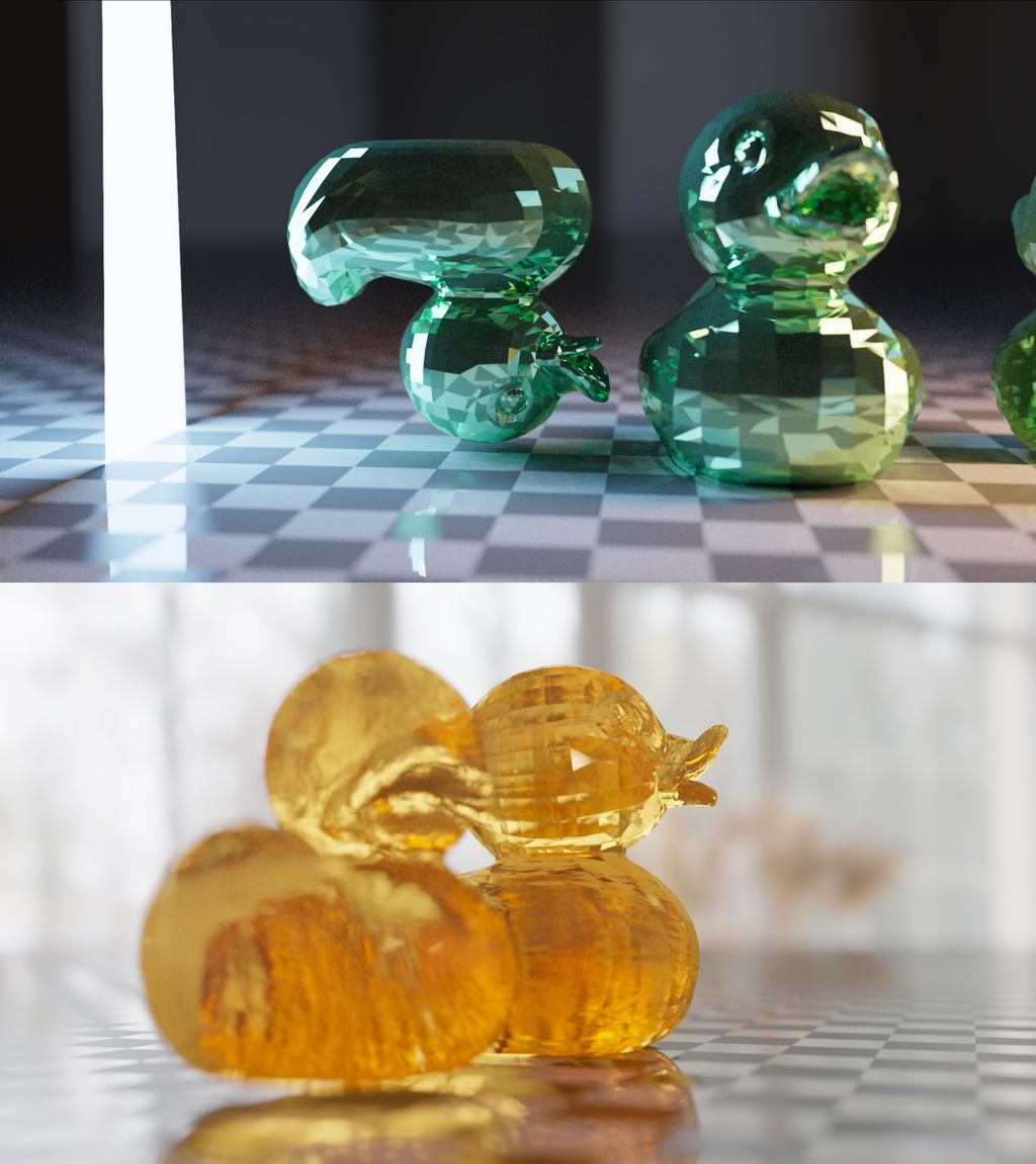
There isn't a ready-to-go implementation of such a rendering technique in Max, but you can make your own path tracer by writing custom shaders. Implementing a path tracer from scratch isn't a trivial task, and it's outside the scope of this article. Still, it shows you that everything is possible in Max, even if no object directly supports a desired functionality (Turing completeness, baby!).
There's still one major problem: finding a good approximation of the solution to the rendering equation requires a lot of time. These images were rendered in about two minutes each. While it may not seem like a lot, it is if we want to render these complex lighting phenomena in real-time, where we just have a few milliseconds of "time budget" to spend on a video frame. Techniques like path tracing are (partially) out of the way if we want to program a real-time application, but we can use many variations of the rendering equation to perform complex shading in the real-time domain.
Let's see some of these techniques and explore which objects implement them.
Ambient occlusion
Ambient occlusion is a method for rendering indirect illumination based on a series of simplifications of the rendering equation. If we assume that every point in our scene is receiving the same amount of light everywhere, that there are no emissive objects, and that we ignore the materials' BRDFs, then the rendering equation simplifies to:
is the so-called ambient light, a constant and uniform light that comes from every direction and which can potentially reach and illuminate any point in the scene. While this may sound like a crude approximation of the lighting phenomenon, it's not too far from the truth: after multiple bounces off surfaces, indirect light looks like a sort of "light reverb," which tends to stabilize around an average value.
The rendering equation looks much simpler now, but we can rework it even further:
The integral has been substituted with a computable discrete summation (Monte Carlo method), and the ambient term has been moved outside it since it's always the same for any incoming light direction. We assumed that the ambient light is uniform and coming from every direction within the normal-oriented hemisphere. We don't care anymore about the angle formed by the surface normal and the incoming light direction. Instead, all we care about is if the light coming from direction can actually reach the point we're shading, or if it's blocked by something. We can, therefore, get rid of the geometric term and substitute it with a simpler occlusion term:
The occlusion term is the result of the function , which returns the value 1 if there's no occluding object looking from position in direction , and 0 if something is blocking the ambient light in the direction.
In some ambient occlusion implementations, the occlusion function doesn't only return a boolean value 0 - 1, but it also reports the distance of the occluding objects.
In practice, this means for every point to explore directions within the hemisphere and count how many of them are occluded.
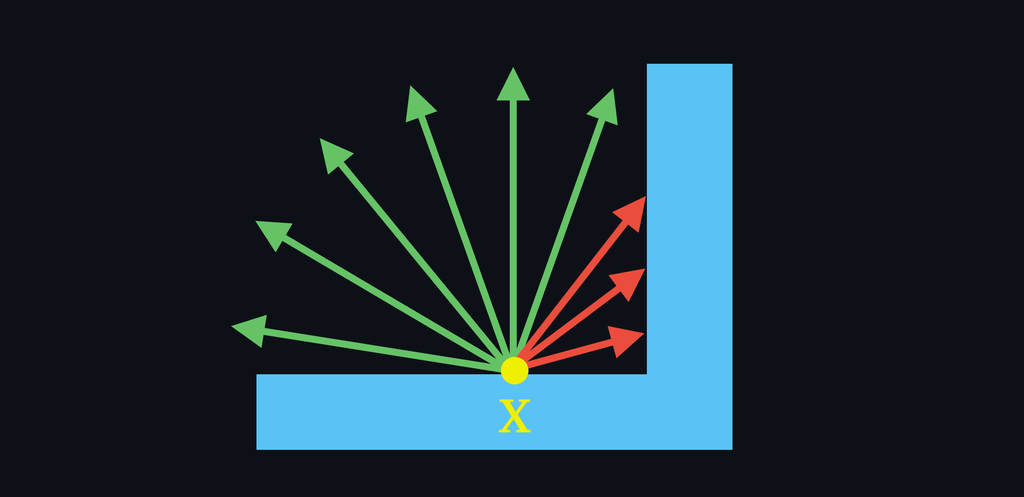
Since the occlusion term is divided by , we compute the average occlusion for point , which is nothing more than a value in the range [0-1] that represents how much "stuff" is blocking the light reaching point .
This is what the occlusion term looks like:
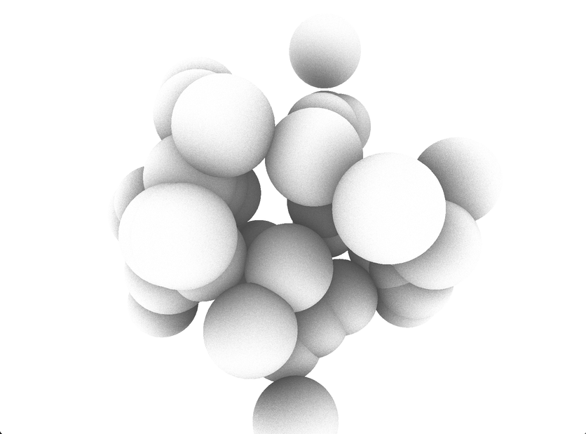
It always impresses me how good the occlusion term looks on its own; it gives the sense of how much indirect light contributes to the perception of objects' volume and distance between each other.
And this is how ambient occlusion changes the look of a scene:

Now that we have a good idea of what ambient occlusion is, let's see which Max objects we can use to implement it. There are three ways for adding ambient occlusion to your rendering, and they take the form of three distinct jit.gl.pass FXs:
- ssao
- tssao-gi
- tssao-gi-ssr
ssao
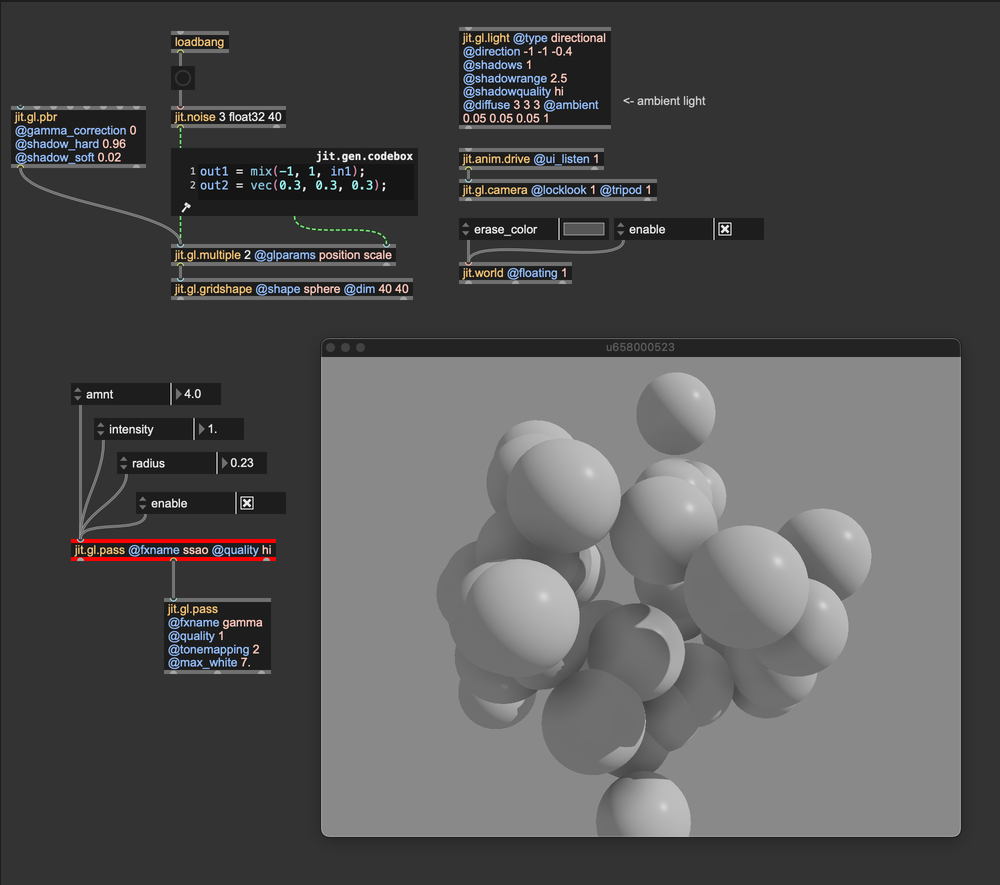
jit.gl.pass' FX ssao is the most straightforward ambient occlusion implementation available in Max. It is controlled by three parameters: amnt, intensity, and radius. Personally, I like to leave intensity at 1, and play around with the other two parameters, but I invite you to explore the settings further. The amnt parameter controls the amount of obscurance, and radius sets the distance to search for occluders. Although simple, ssao is my first choice because it's not demanding in terms of computing resources, and with a bit of tweaking, it can perform miracles.
Try to cascade three ssao FXs with decreasing radius. I find this configuration to be the best, as it delivers near-surface details but also reacts to distant occluders.
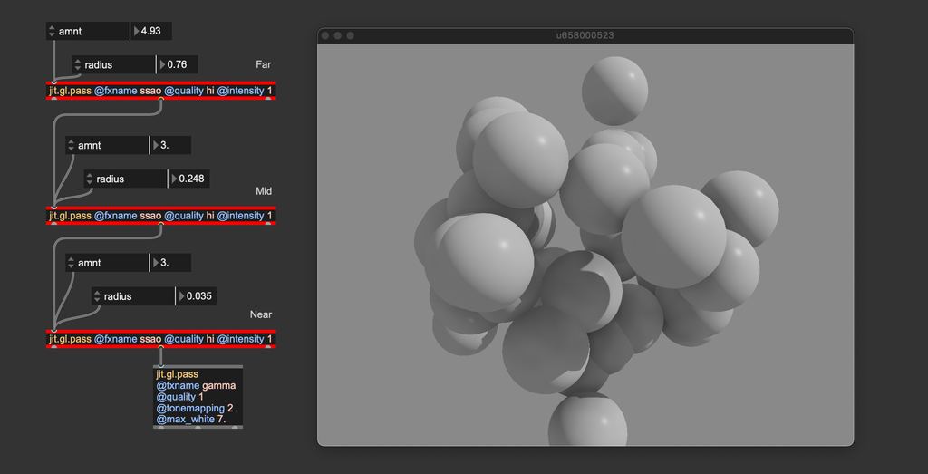
The effect's name is an acronym for Screen-Space Ambient Occlusion, a technique for exploring the vicinity of each pixel in search of potential occluders.
tssao-gi and tssao-gi-ssr
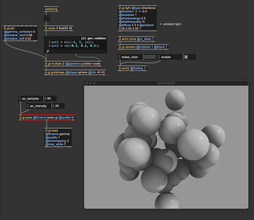
If computing power isn't an issue, you can use the jit.gl.pass FXs tssao-gi and its "expanded" version tssao-gi-ssr. Although different at the implementation level from ssao, these two FXs compute ambient occlusion according to the same principles. The main difference is that tssao-gi and tssao-gi-ssr gather the color of the occluding objects, better approximating the indirect light components.
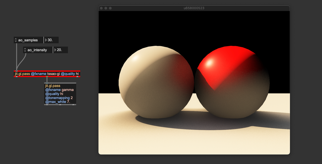
You can see how the red sphere reflects some light onto the white sphere and that the floor illuminates both spheres from below. The tssao-gi-ssr variation adds reflections to the result; in a separate step, the FX assumes all surfaces have the same specular BRDF and computes the amount of reflected color.
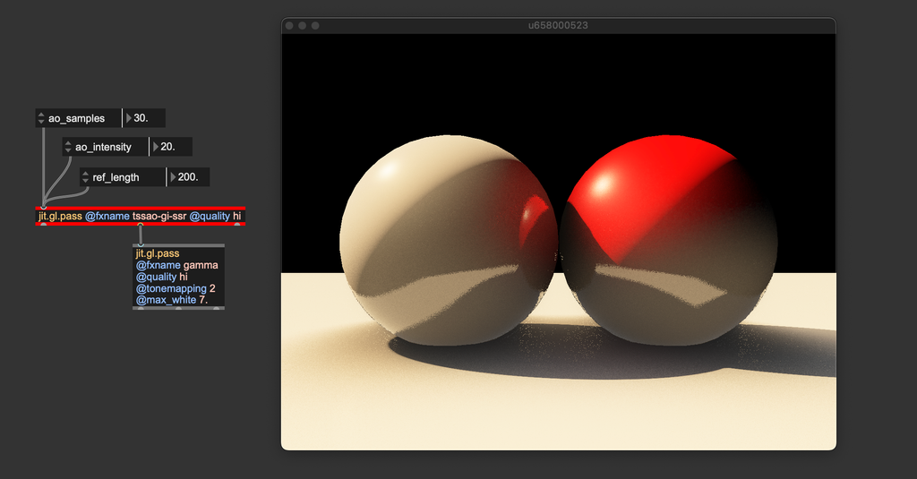
"tssao" stands for Temporal Screen-Space Amient Occlusion, "gi" for Global Illumination, and "ssr" for Screen-Space Reflections. These two pass FXs can get closer to the original rendering equation formulation, but many aspects remain unconsidered (e.g., albedo modulation and per-surface BRDFs).
Before moving on, let's talk about how to set the ambient light values for jit.gl.light. Light loses some energy at each bounce because part of it gets absorbed (the amount of absorption depends on the albedo values of the surface it bounced off). After a few reflections (like 7 or 8), radiance typically becomes very weak, negligible in terms of lighting contribution. Since the ambient light should represent the average indirect light amount, its values are usually relatively low (in the above examples, R: 0.05, G: 0.05, B: 0.05). In other words, don't be afraid to use small values for ambient light.
Personally, I recommend starting with the ambient light set to 0 and gradually increasing it until you achieve the desired effect. If your scene includes a colored background (e.g., @erase_color 0.1 0.1 0.4 1.0), try matching the ambient light's tint to the background color. This approach helps create the impression that the environment is contributing to the scene's illumination. For an even spicier technique, consider using jit.fx.an.mean to calculate the average color of the rendered image and apply it as the ambient light.
ReSTIR
![Image rendered using [jit.gl.pass @fxname gi]. Left: direct illumination only (jit.gl.pbr + jit.gl.light); right: direct illumination + indirect illumination](/images/d464ab697aca50f143625a4d09938490_1024.webp)
ReSTIR (Reservoir-based Spatio-Temporal Importance Resampling) is a cutting-edge technique in real-time computer graphics for improving lighting quality. It's especially valuable for ray-traced graphics, where simulating light behavior accurately is traditionally very demanding on computational resources.
Let’s explore what makes ReSTIR unique without delving too deep into the technical details. When we discussed path tracing, we noted that this rendering method is slow because it requires evaluating a large number of incoming light directions to approximate the solution to the rendering equation, which makes it unsuitable for real-time applications. So, how many directions can we feasibly evaluate within the time span of a single frame on modern hardware? The answer is surprisingly limited: just one or two. Given that a typical path tracer samples around 10,000 directions, which single direction should we prioritize? Ideally, it would be the direction that carries the most energy (light), contributing the most to the pixel’s shading. But how can we identify this optimal direction? This is where ReSTIR comes into play. Think of it as a sophisticated 'direction sorter' that can quickly identify the most significant light direction—the one that maximizes energy contribution.
Numerous variations of the ReSTIR algorithm have been developed to adapt to different rendering pipelines. In Jitter, the ReSTIR algorithm is used to compute global illumination by tracing rays in screen-space.
ReSTIR has been implemented in Max 9 as jit.gl.pass FX named "gi" (global illumination). This pass FX can interact with jit.gl.pbr (to get the materials' BRDFs) and with jit.gl.environment (to gather light from an environment map). This means that whichever settings you use for jit.gl.pbr, the ReSTIR algorithm will respond with the correct lighting behavior. For example, any change of a mesh' roughness and/or metalness will affect how the "gi" pass computes global illumination.
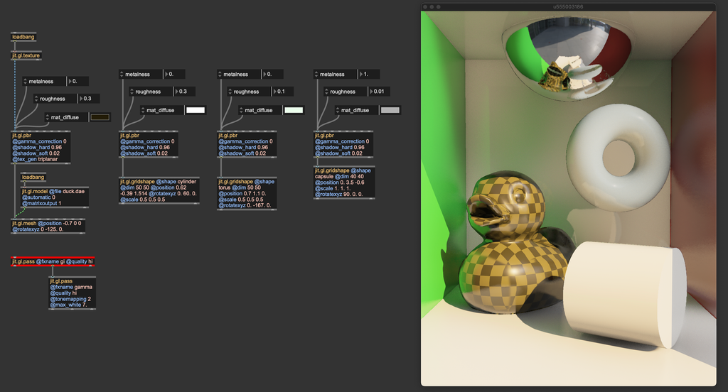
The inner mechanics of the ReSTIR algorithm are complex, but the "gi" pass FX is relatively straightforward to use. As long as you correctly set gamma correction and tonemapping, you just need to instantiate it, and it does its job.
The "gi" pass FX requires rendering multiple render targets (direct illumination, albedo, normals, roughness, metalness, four layers of depth). To make the effect work correctly, the jit.gl.pass @quality attribute must be set to "hi".
Some of the effects discussed in this chapter, particularly "tssao-gi" and "gi," compute indirect illumination by simulating the way light bounces off surfaces in the scene. The amount of light reflected back into the environment after each bounce is influenced by several factors, one of which is the albedo color—often referred to as the surface color (corresponding to the attribute @mat_diffuse in jit.gl.pbr and jit.gl.material).
The term "albedo color" can be somewhat misleading, as it might suggest it is simply a color. In reality, the albedo color determines the proportion of light that is absorbed versus reflected by a surface. For example, an albedo color of (0.9,0.1,0.1) (RGB) indicates that the object reflects nearly all energy in the red wavelength while almost completely absorbing the green and blue wavelengths.
With this in mind, it’s crucial to be careful when setting the albedo color:
- The albedo color should not exceed a value of 1. In accordance with the principle of energy conservation, no object can reflect more light than it receives.
- The albedo color should also avoid being exactly 0 or 1. In the physical world, no object perfectly absorbs or reflects a specific wavelength. To avoid this, avoid absolute values when setting albedo. For example, instead of defining a bright green surface as (0.0, 1.0, 0.0), use a value like (0.05, 0.9, 0.05). This ensures no wavelength is completely "eliminated," which is particularly important if the indirect illumination algorithm in use calculates multiple light bounces.
- Albedo values generally do not need to be very high. Typically, albedo colors are defined with values below 0.5. If you need a brighter appearance, consider increasing the light intensity instead of pushing albedo values higher.
These are the built-in solutions for computing indirect lighting and global illumination in Max 9. However, there are other noteworthy algorithms and strategies for global illumination, such as voxel cone tracing (VCT), surfels, virtual point lights (VPL), and instant radiosity, each with its own set of pros and cons. So, which method is the best? It depends on the situation—use what works best for your needs; and if the built-in global illumination options in Max 9 don’t meet your requirements, I encourage you to implement your own using custom shaders. All the effects discussed in this article were originally prototyped with Max objects.
Image-based lighting

One of the secrets to achieving realism is Image-Based Lighting, or IBL for short. Think of IBL as a way to light up your 3D world using real photos of an environment. Instead of manually placing lights around your scene, you can use an image, often a special panoramic photo called an environment map (a High Dynamic Range image), that captures the light and colors of a real place. This image wraps around your 3D scene like an invisible sphere, casting light and reflections as if your virtual object were truly sitting in that environment.
In Max you can upload an environment map into jit.gl.material or jit.gl.pbr directly, or use jit.gl.environment. The latter is designed to communicate with all jit.gl.pbr, jit.gl.material, and jit.gl.skybox objects in the patch. jit.gl.environment also interacts with the "gi" pass FX. By loading an environment map, the "gi" pass can ray trace this environment, casting light from it.
Usually, all objects in a 3D scene are supposed to live in the same environment. For this reason, it's often best to use jit.gl.environment for uploading an environment map, because it greatly simplifies the IBL settings.

By loading different environment maps, you can quickly change the illumination of your entire scene. You can download plenty of them online or create your own with 360° cameras. Environment maps usually come in the .EXR format.
EXR images, or OpenEXR files, are a type of image format designed specifically for high-quality, high-dynamic-range (HDR) imaging. These images are commonly used in computer graphics and visual effects, including environment mapping, due to their ability to store a vast range of luminance and color data that traditional image formats like JPEG or PNG cannot capture.
Environment maps usually come in two formats: equirectangular and cube maps.
-
An equirectangular environment map is a panoramic image representing a full 360-degree view of an environment mapped onto a 2D rectangular image. The format resembles a world map where the top and bottom portions correspond to the poles, and the center represents the equator.
-
A cube map is a set of six square images that represent the environment around a point in space. Each image covers one side of a cube (front, back, left, right, top, and bottom). When mapped together, these six images form a seamless 3D environment around a viewer or object.
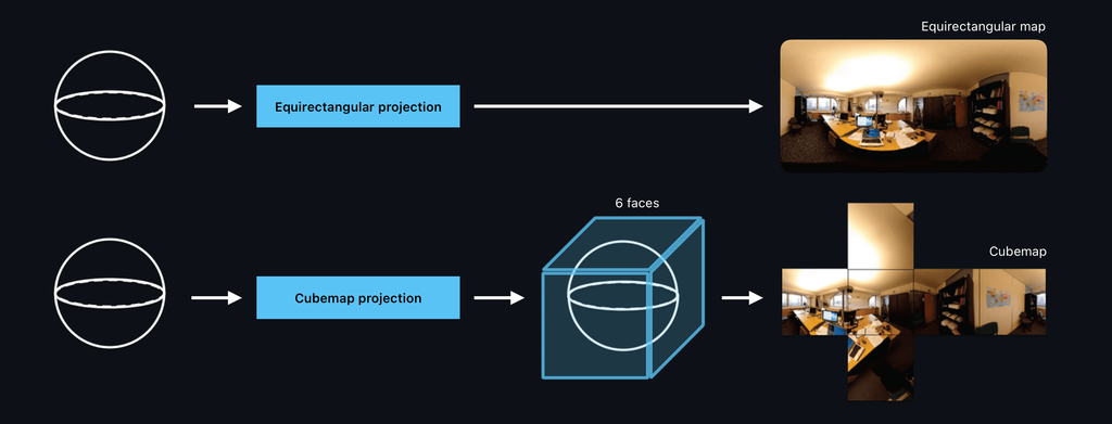
The object jit.gl.environment can load equirectangular environment maps. Still, if you have a cube map, you can transform it into an equirectangular map using the object jit.gl.cubemap.
Take a look at the jit.gl.environment help file to see how to import cube maps into it. If you need to transform an equirectangular environment map into a cube map, check out the "ibl.rect2cube.mrt.jxs" shader.
The object jit.gl.environment has a @gamma_correction attribute. Like with jit.gl.pbr, if you want to manage gamma correction manually, you should disable this attribute. The jit.gl.environment object includes an attribute called @reflect_edge, which determines the resolution of the environment map used for reflections. This value should be set as a power of 2.
If your scene contains very smooth materials (with @roughness close to 0), a low @reflect_edge value may result in blurry reflections. If that's the case, increase @reflect_edge to a larger power of two.

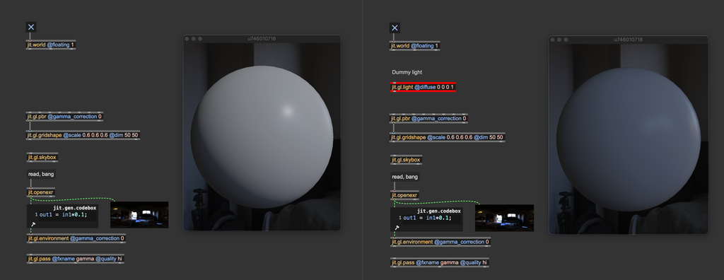
Max comes with a built-in "default" lighting setup. When you create a 3D object in an empty patch, it appears illuminated even if no jit.gl.light object is present. This is because Max automatically applies a white hemisphere light from above, providing a convenient way to sketch out a scene without worrying about lighting configuration. However, as soon as you add a jit.gl.light object, this default light is automatically turned off and replaced by the your custom, user-defined light. Unlike with jit.gl.light objects, the default light isn’t automatically disabled when using a jit.gl.environment.
If you want to use image-based lighting ONLY (without any jit.gl.light), you must instantiate a "dummy" light with @diffuse 0 0 0 to override the default hemisphere light.
Shadows
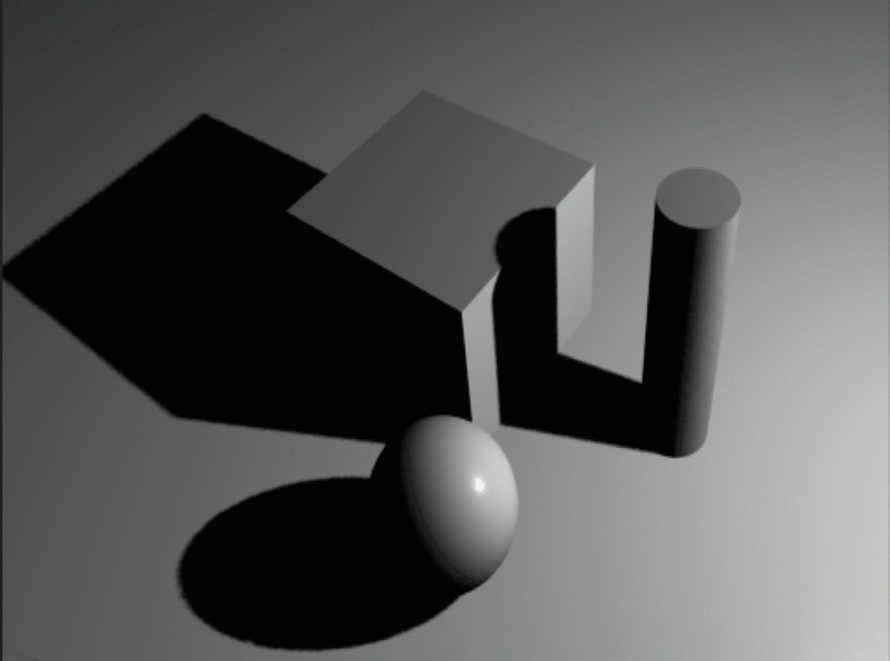
In computer graphics, shadows are visual indicators that mimic the effect of objects blocking light. They are crucial for creating realistic 3D environments as they convey the spatial relationships between objects, their positions, and their interactions with light sources. Shadows result from light being obstructed and unable to reach certain surfaces. In essence, shadows are defined negatively: they represent the absence of light. The rendering equation inherently accounts for shadowing, but, as mentioned, solving it directly is impractical in real-time rendering. Therefore, specific techniques have been developed to identify which surfaces should not be illuminated. Jitter employs a method known as shadow mapping for rendering shadows.
Shadow mapping works by identifying which parts of the scene are occluded from the light source's viewpoint, thus indicating where shadows should fall. Due to its versatility, this method is highly effective and widely used in real-time rendering for applications like video games and simulations. Imagine positioning a light source (e.g., jit.gl.light) and observing the scene from its vantage point. Surfaces visible from the light’s position receive illumination, while those not directly seen remain in shadow.
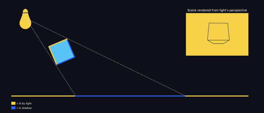
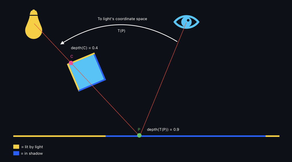
Shadow maps are created by rendering the scene from the light's point of view and recording the distance to the visible surfaces. To determine if a point visible from the camera should be in shadow, the distance from that point to the light source is calculated. If this distance is greater than the value stored in the shadow map, the point is considered in shadow.
Let's see how to activate shadows in Jitter:

Shadows are activated from the jit.gl.light object by enabling the @shadows attribute. All 3D objects connected to a jit.gl.pbr or jit.gl.material will cast and receive shadows.
Only directional lights and spot lights can cast shadows.
Shadows are there, but they don't look very good in this scene and would probably need some tweaking. jit.gl.light has some attributes we can modify related to shadows: @shadowblur, @shadowquality, @shadowrange. Let's see what are these attributes refer to:
@shadowblur controls the amount of blurring applied on the rendered shadows. When the light source is very small or very far from the illuminated object, shadows appear sharp, with well-defined edges where the transition between light and shadow is abrupt. This kind of shadow is usually called hard shadows. On the contrary, if the light has a big emitting surface, shadows have blurred, gradual edges, creating a transition zone between light and dark. This transition is called the penumbra, where light is partially blocked but not wholly absent. The center of the shadow, where light is entirely blocked, is called the umbra. Such blurry shadows are called soft shadows. The @shadowblur attribute controls the transitions from hard to soft shadows, and it helps give the impression of a large emitting light. It also helps with masking aliasing problems (more on that later).

@shadowquality is a parameter that controls the resolution of the shadow map. As said before, shadow mapping captures the scene from the camera's point of view into a texture. @shadowquality sets the overall quality of the shadow map by changing its resolution.

When setting @shadowquality, start from "hi", and progressively reduce the quality until you see jagged shadow margins. Then, increase the quality by one step. If performance isn't an issue, go with "hi" directly.
Instead of using the @shadowquality attribute, you can send the message [sendoutput dim followed by the desired shadow map size to jit.gl.light. Take a look at the patch "lights.shadow.map.texture.maxpat" for an example.
The @shadowrange attribute determines how much of the scene is visible from the light's perspective. When rendering the scene from a light source, the light is represented by a virtual camera, which has the same controls as any camera created with jit.gl.camera. This includes a far clip parameter to set the extent of the view frustum. The @shadowrange attribute specifies the length of the light-camera frustum. Adjusting this attribute properly is essential to ensure that all objects in the scene can cast shadows.

From left to right: @shadowrange too short, correct @shadowrange, @shadowrange too long.
When @shadowrange is too small, only objects close to the light can cast shadows. When @shadowrange is too high, all objects in the scene can cast shadows, but the produced shadows lack definition.
When setting @shadowrange, start at 0 and increase it slowly. Stop right when all objects in the scene are casting shadows.
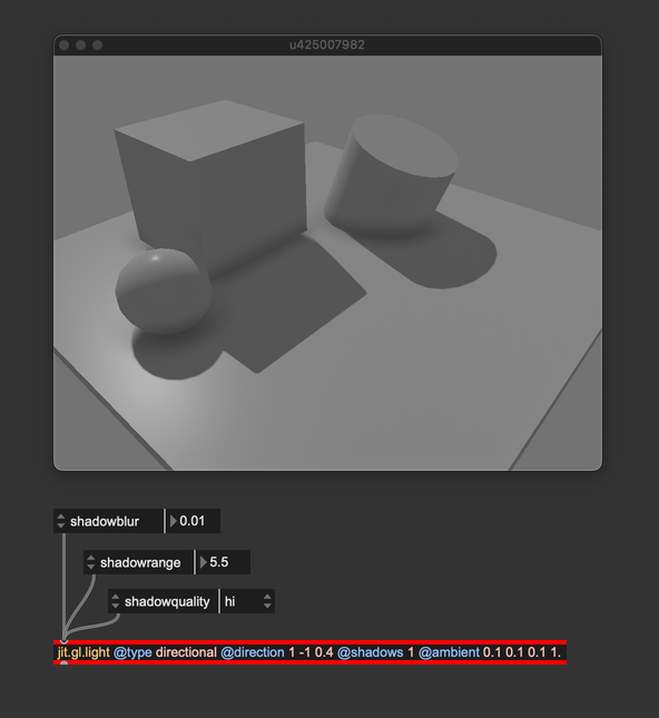
Personally, I usually like to have shadows with no or little blur when using directional lights because they simulate light coming from a distant emitter, which doesn't create penumbra regions. @shadowrange has been set to comprise all the objects in the shadowmap tightly, and @shadowquality has been set to "hi" because performance wasn't problematic with such a simple scene.
These were the shadow settings of jit.gl.light, but there are other shadow-related attributes we can modify: jit.gl.pbr and jit.gl.material can in fact be used to tweak the shadow apparence further. Let's take a closer look at our scene:
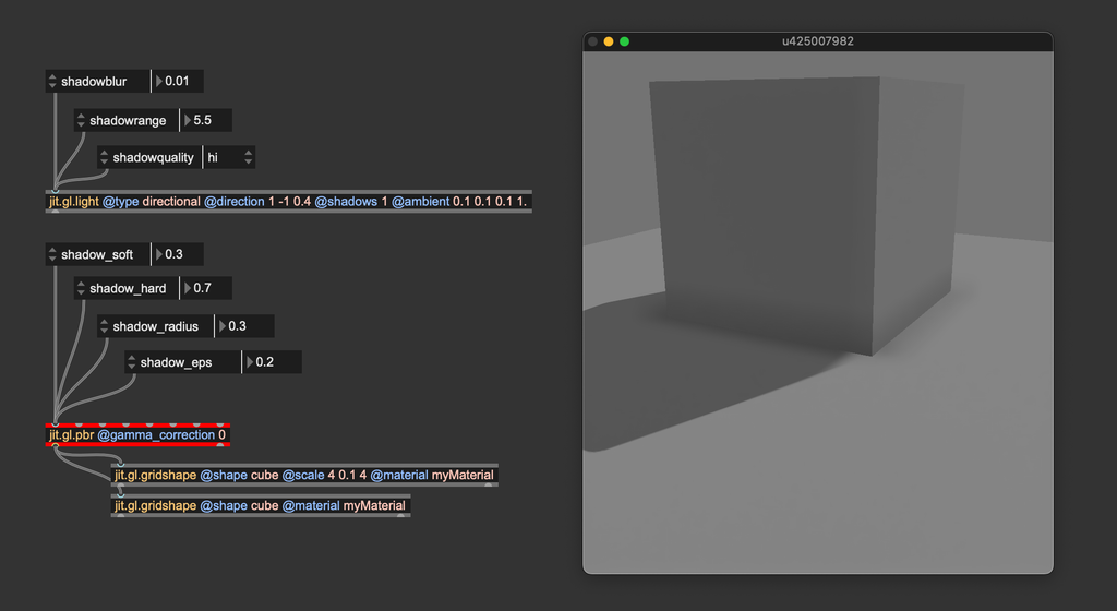
You can notice that the shadow isn't precise where the cube contacts the floor. jit.gl.pbr's shadow-related attributes control the behavior of the shadow-receiving objects, and we can try to tweak them to improve the shadow's look. @shadow_hard, @shadow_soft, and @shadow_radius are parameters used to trim the shadow's appearance when jit.gl.light's @shadowblur is greater than 0, defining the transition between umbra and penumbra. Since our light is directional, we should set these parameters to their "neutral" values:
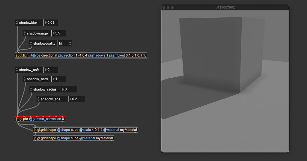
You can see that the contact shadow looks sharper now. The last attribute, @shadow_eps, is used to compensate for two kinds of visual artifacts that shadow mapping may produce: shadow acne and light leakage.
Shadow acne is a common artifact in shadow mapping. It creates an unwanted pattern of dark spots or lines on the surfaces of 3D objects.
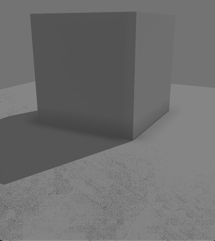
This issue happens when the shadow map incorrectly calculates whether a point is in shadow, leading to a speckled or "striped" appearance. Shadow acne arises due to precision errors and self-shadowing issues. When rendering from the light's point of view, each surface's distance from the light is stored in the shadow map. The distance from the camera's perspective is compared to the shadow map's stored values during the scene's final rendering. If the depth values are too close or nearly identical, slight precision errors can cause the surface to be falsely considered in shadow, even when it shouldn't be. This leads to shadow acne. A slight offset is added to the distance comparison to solve this issue, removing self-shading issues. @shadow_eps controls this arbitrary offset (the slight offset is usually called "epsilon").
Light leakage is another common artifact in shadow mapping. In this phenomenon, light unintentionally "leaks" through objects, causing parts of the scene to appear illuminated when they should be in shadow.
Light leakage typically happens due to improper depth comparisons or insufficient precision in the shadow map, leading to errors in identifying whether a surface should be in shadow. This issue is especially common when large or complex scenes are rendered, where distant objects or parts of the scene may not be accurately represented in the shadow map. Light leakage arises when @shadow_eps is too high.
When setting @shadow_eps, start at 0 and increase it slowly. Stop right when the artifacts disappear.
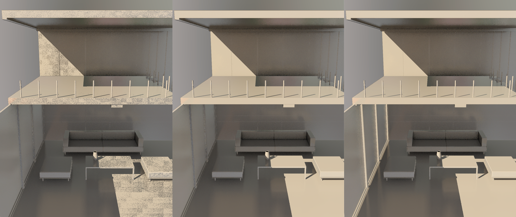
Left: @shadow_eps = 0, leads to shadow acne; Center: @shadow_eps 0.004, correct settings for this scene; Right: @shadow_eps = 0.2 (the default), leads to light leaking through the wall on the left, and the shadows below the poles on the balcony look detached from the poles.
At the end of the day, shadow mapping always requires some tweaking. It's impossible to find settings that always work because shadow mapping is very sensitive to the scene's scale. The only way to get the desired effect is to empirically tweak the parameters until the shadows look good. Still, it's important to know what each parameter is doing in order to understand how to adjust it.
As with everything in computer graphics, the original algorithm has lead to many variations and innovations. For example, we have percentage-close filtering (PCF), variance shadow maps (VSM), and cascaded shadow maps (CSM). For those of you who are into shader programming, we invite you to experiment with different shadow mapping techniques. If you need to access the shadow map captured by jit.gl.light for custom shadow mapping implementations, check out the patch 'lights.shadow.map.texture.maxpat'.
In summary
- Consider using a method to simulate indirect lighting.
- jit.gl.pass' FXs
ssao,tssao-gi, andtssao-gi-ssrimplement variations of the ambient occlusion algorithm. - jit.gl.pass' FX
giimplements a ReSTIR algorithm for computing global illumination and requires@quality hi. - When setting albedo values (
@mat_diffuse), stay away from pure colors (don't use exactly 0 or 1), and prefer low albedo values (<= 0.5); if you need a brighter color, consider increasing light's intensity instead. - Disable jit.gl.environment's
@gamma_correctionif you want to manage gamma correction manually. - Set jit.gl.environment's
@reflect_edgeto a large power of two if the scene contains smooth materials. - Instantiate a black light (
@diffuse 0. 0. 0.) if you need to use image-based lighting only. - Tweak jit.gl.light's
@shadowblur,@shadowquality, and@shadowrangeto fine tune shadow mapping for your scene. - Set jit.gl.pbr's
@shadow_hard,@shadow_soft, and@shadowblurto control shadows's apparence. - Adjust jit.gl.pbr's
@shadow_epsto remove shadow mapping artifacts.
To learn more about
The rendering equation, BRDF, PBR, IBL, and path tracing
- https://www.youtube.com/watch?v=gsZiJeaMO48
- https://www.youtube.com/watch?v=Qz0KTGYJtUk&t=154s
- https://www.youtube.com/watch?v=KkOkx0FiHDA&ab_channel=Acerola
- https://blog.demofox.org/category/path-tracing/
- https://raytracing.github.io/books/RayTracingInOneWeekend.html
- https://www.youtube.com/watch?v=qW6rJ0s2Xv0&list=PLplnkTzzqsZS3R5DjmCQsqupu43oS9CFN&index=26&ab_channel=CemYuksel
- https://www.youtube.com/watch?v=gfW1Fhd9u9Q&list=PLlrATfBNZ98edc5GshdBtREv5asFW3yXl&ab_channel=TheCherno
- https://learnopengl.com/PBR/Theory
- https://en.wikipedia.org/wiki/Bidirectional_reflectance_distribution_function
- https://graphicrants.blogspot.com/2013/08/specular-brdf-reference.html
- https://cglearn.eu/pub/advanced-computer-graphics/physically-based-shading
More about ReSTIR
- https://www.youtube.com/watch?v=gsZiJeaMO48
- https://interplayoflight.wordpress.com/2023/12/17/a-gentler-introduction-to-restir/
- https://intro-to-restir.cwyman.org
- https://research.nvidia.com/sites/default/files/pubs/2020-07_Spatiotemporal-reservoir-resampling/ReSTIR.pdf
- http://www.zyanidelab.com/restir-gi-for-specular-bounces/
- https://research.nvidia.com/publication/2021-06_restir-gi-path-resampling-real-time-path-tracing
- http://www.zyanidelab.com/how-to-add-thousands-of-lights-to-your-renderer/
- https://www.youtube.com/watch?v=QWsfohf0Bqk
Ambient occlusion and global illumination
- https://www.youtube.com/watch?v=teB-pbAd8JE&list=PLplnkTzzqsZS3R5DjmCQsqupu43oS9CFN&index=23&ab_channel=CemYuksel
- https://www.youtube.com/watch?v=zlM4bMwqtCk&list=PLplnkTzzqsZS3R5DjmCQsqupu43oS9CFN&index=22&ab_channel=CemYuksel
- https://en.wikipedia.org/wiki/Ambient_occlusion
- https://learnopengl.com/Advanced-Lighting/SSAO
- https://publik.tuwien.ac.at/files/PubDat_191582.pdf