Examples
Display a signal or plot two signals in X-Y mode
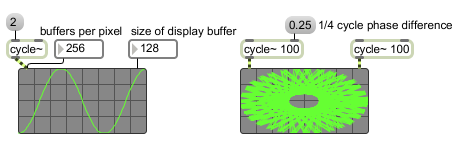
Signal oscilloscope
| int | object-settings [int] |
In left inlet: Sets the number of samples collected for each value in the display buffer. Smaller numbers expand the image but make it scroll by on the screen faster. The minimum value is 2, the maximum is 8092, and the default initial value is 256. In X or Y mode, the most maximum or minimum value seen within this period is used. In X-Y mode, a representative sample from this period is used. In right inlet: Sets the size of the display buffer. This controls the rate at which scope~ redisplays new information as well as the scaling of that information. If the buffer size is larger, the signal image will stay on the screen longer and be visually compressed. If the buffer size is smaller, the signal image will stay on the screen a shorter time before it is refreshed and will be visually expanded. It might appear that the samples per display buffer element and the display buffer size controls do the same thing but they have subtly different effects. You may need to experiment with both controls to find the optimum display parameters for your application. |
| (mouse) | When you click on a scope~, its display freezes for as long as you hold the mouse button down. | |
| signal | In left inlet: The input signal is displayed on the X axis of the oscilloscope. In right inlet: The input signal is displayed on the Y axis of the oscilloscope. If signal objects are connected to both the left and right inlets, scope~ operates in X-Y mode, plotting points whose horizontal position corresponds to the value of the signal coming into the left (X) inlet and whose vertical position corresponds to the value of the signal coming into the right (Y) inlet. If the two signals are identical and in phase, a straight line increasing from left to right will be seen. If the two signals are identical and 180 degrees out of phase, a straight line decreasing from left to right will be seen. Other combinations may produce circles, ellipses, and Lissajous figures. |
| Name | Type | g/s | Description |
|---|---|---|---|
| bgcolor | float | Sets the background color of the scope~ object's display in RGBA format. | |
| bordercolor | float | Sets the border color of the scope~ object's display in RGBA format. | |
| bufsize | int def.:128 |
Sets the number of samples stored in the buffer used by the scope~ object. | |
| calccount | int def.:256 |
Sets the number of samples per pixel displayed by the scope~ object. The default is 256. | |
| delay | float def.:0. |
Sets the number of milliseconds of delay before scope~ begins collecting values. After a non-zero delay period, scope~ enters a state in which it may wait for a trigger condition to be satisfied in the input signal based on the setting of the trigger state (set with the trigger message) and trigger level (set with the message). By default, the delay is 0. | |
| drawstyle | int def.:0 |
Toggles an alternate drawing style for the scope~ object which may make some waveforms more easily visible. The default is off (). | |
| fgcolor | float | Sets the waveform display color of the scope~ object in RGBA format. | |
| gridcolor | float | Sets the grid color of the scope~ object in RGBA format. | |
| range | float def.:-1. 1. |
Sets the minimum and maximum signal amplitudes displayed by the scope~ object. The default values are -1 to 1. | |
| rounded | int def.:8 |
Sets the radius size in pixels for the corners of the panel object. | |
| trigger | int def.:0 |
Sets the trigger mode. After a non-zero delay period (set with the message), scope~ begins to wait for a particular feature in the input signal before it begins collecting samples. sets an upward trigger in which the signal must go from being below the trigger level (default 0) to being equal to it or above it. sets a downward trigger in which the signal must go from being above the trigger level to being equal to it or below it. The default trigger mode is 0, which does not wait after a non-zero delay period before collecting samples again. This is sometimes referred to as a "line" trigger mode. | |
| triglevel | float def.:0. |
Sets the trigger level, used by trigger modes 1 and 2. The default trigger level is 0. If you are displaying a waveform, making slight changes to the trigger level will move the waveform to the left or right inside the scope~. It is possible to set the trigger level so that scope~ will never change the display. |
| Name | Description |
|---|---|
| meter~ | Visual peak level indicator |
| MSP Tutorial 24: Oscilloscope | MSP Tutorial 24: Oscilloscope |