Intro
In this section we’ll use the Jitter Matrix to create 3D geometry instead of video. We can define XYZ points in virtual space in a way similar to how we define RGB color values in cells of a matrix, and then use that to draw 3D shapes. While the char data type (numbers in the range 0-255) works well for color, we'll need much greater precision for 3D coordinates - so we'll use the float32 (32-bit floating point) data types for our matrices.
Setup
Begin with the usual named jit.world and toggle object pair.
Mesh generation - simple, using Jit.gl.mesh, jit.noise and the float32 matrix
Click on the toggle to turn on your jit.world and add a jit.gl.mesh @lighting_enable 1 object. You'll notice that adding the jit.gl.mesh object doesn’t automatically display anything by itself - this is because it’s waiting for a matrix to tell it what to draw. The jit.gl.mesh object takes in any floating point matrix with 3 or more planes (we'll discuss those extra planes in later tutorials) and interprets them as OpenGL primitive shapes.
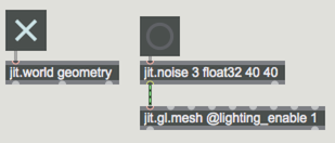
Now add a jit.noise 3 float32 20 20 object. This gives us 3 planes for x, y and z and a 20 x 20 grid of 400 points. Add a button above to trigger the noise. Connect the jit.noise to the left inlet of the jit.gl.mesh object and then lock the patch. Turn on your jit.world and click the on the button - you should see a chaotic ball of shards filling the upper right corner of your render window.
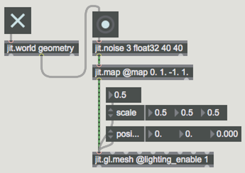
You’ll notice it’s only rendering shapes in the upper right-hand area of the window. That's because the jit.noise outputs values ranging from 0. - 1. In OpenGL, the center is always a “0. 0. 0.” Positive x goes right, negative x goes left, while positive y goes up, negative down, and positive z goes forward (or away) and negative goes back. To fill out the screen a little better, add a jit.map @map 0. 1. -1. 1. object between jit.noise and jit.gl.mesh. The jit.map objects works similarly to scale on Jitter Matrix values.
Add a scale attrui to your jit.gl.mesh object so you can adjust the size and fit it on screen. Finally, connect the middle outlet of jit.world to your jit.noise object to animate it.
Matrixoutput
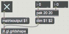
Now that we’ve created chaos, let’s use an object from earlier to generate a more structured output. Create a jit.gl.gridshape object and add a message (or attrui) to control its matrixoutput attribute and another for dim <x,y>, then add a jit.pwindow below and connect to it from the gridshape object. It will not appear in your render window until you set the matrixoutput to 1 - add a toggle and turn it on.
You can now see the x, y, z data displayed in the pwindow as RGB values. As with our jit.noise object, this matrix data is float32 and describes the geometry of the shape selected.
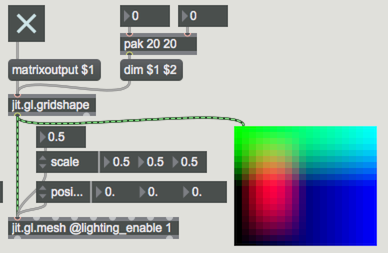
Add another jit.gl.mesh object (with lighting) and connect the jit.gl.gridshape object’s output into the left inlet to see it. Again - you may want to adjust scale and position so you can see both objects on the screen.
Drawermodes
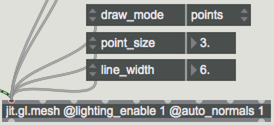
Using the geometry data from jit.gl.gridshape with jit.gl.mesh provides us with some extra options - add an attrui to your mesh object and select the draw_mode attribute. These modes determine how the points in your geometry are connected to each other to create your form. The default is quad_grid, which interprets the matrix as a surface that is filled in with quads. Try some of the other options to see what’s available. Increasing the dim attribute of the jit.gl.gridshape will allow you to increase or decrease the number of points and thus the resulting image. You can also adjust the point_size with drawmode points and line_width with drawmode lines, line_strip or line_loop to further modify the look.
Manipulating the geometry
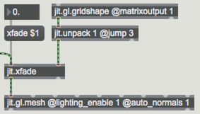
The geometry data we get from jit.gl.gridshape is really just an array of floating point values, so we can manipulate it any way we'd like before we send it to jit.gl.mesh for rendering. The jit.gl.gridshape object outputs a 12-plane matrix. You’ll learn more about this in later tutorials, but for now we only need the first three planes of the matrix, which store x, y and z values. Make a jit.unpack 1 @jump 3 object and connect the output of jit.gl.gridshape to it. Now add a jit.xfade object with a message box containing message and a flonum (or attrui) connected. Patch the left outlet of jit.noise into the left inlet and the outlet of jit.unpack into the right. Disconnect the jit.gl.gridshape from the jit.gl.mesh, replacing it with the output of jit.xfade. Try adjusting the xfade value from 0. - 1. to see how the two matrices modify each other. A 0. will be the pure noise, and a 1. will be the gridshape, but anything else will be a combination of the two.
To smooth out the transformations caused by jit.noise, add a jit.slide @slide_up 10 @slide_down 10 object and add controls for the slide_up and slide_down attributes. Adjust the values to see how it changes the form.
Explore Further
Most of the jit.gl.mesh object draw_mode options are actually standard OpenGL primitives, designed to make it lightweight for an array of values to be sent and interpreted in a specific way instead of making a separate call for each triangle. Many of the modes are interpreted across the horizontal dimension of the incoming matrix. For example, in polygon mode, each row represents one complete polygon shape. To fully understand how each draw_mode is interpreted, we recommend consulting the OpenGL Red Book or similar references
The jit.gen object is another great way to generate geometry data. Take a look at this patch, which does something very similar to what we created above, but all inside of jit.gen.