This tutorial shows you how to draw and position 3D text in a jit.window object using the jit.gl.text3d and jit.gl.render objects. Along the way, we will cover the basics of drawing OpenGL graphics using the jit.gl.render object.
The jit.gl.text3d object is one of the many Jitter OpenGL drawing objects that work in conjunction with the jit.gl.render object. OpenGL is a cross-platform standard for drawing 2D and 3D graphics, designed to describe images so that they can be drawn by graphics coprocessors. These coprocessors, also known Graphics Processor Units or GPUs, speed up drawing operations enormously, allowing complex scenes made of textured polygons to be animated in real time. OpenGL graphics can help you create faster visual displays or interfaces without bogging down your computer’s CPU.
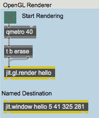
In the lower left of the patch, there is a jit.window object named . This window will be the destination for our OpenGL drawing.
The toggle starts the qmetro object,which sends messages to a trigger object. For each received at its inlet, the trigger object sends the message out its right outlet, and then a message out its left outlet. These messages are sent to the jit.gl.render object.
Creating a Drawing Context
All OpenGL graphics in Jitter are drawn with the aid of jit.gl.render objects. Each jit.gl.render object must refer to a named destination for drawing. You can specify this destination using an initial argument to jit.gl.render. So in this case, jit.gl.render creates a jit.gl.render object that will draw to the destination window that we have named .
We refer to this combination of a jit.gl.render object and a named destination as a drawing context. A drawing context is required for OpenGL rendering. The objects on the left side of this patch are sufficient to build a valid drawing context, and so when you click on the toggle, the message appears in the Max Console. This tells you that the context is being created.
GL Objects in the Context
Common 3D Attributes
All Jitter OpenGL objects (which all begin with "jit.gl") share a common set of attributes that allow them to be positioned in 3D space, colored, and otherwise modified—the GL group (ob3d). Drawing 3D graphics can be a fairly complex task. The ob3d group simplifies this by insuring that the messages you learn to draw one 3D object will work with all of them, whenever possible. These common attributes are fully documented in the GL group section of the Object Reference of any jit.gl object. To introduce the 3D group here, we will demonstrate the position, rotation, scale and axes attributes by manipulating the jit.gl.text3d object.
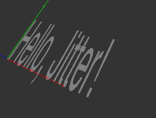
We can add a set of spatial axes to the jit.gl.text3d object to make our spatial manipulations easier to see and understand—it's both easier to see how the text object is oriented, and also to see additional information about exactly where the object’s origin is.
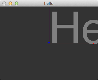
The x axis, drawn in in red, points to the right. Zero is at the center of the screen, and increasing x values move in the direction of the right of the screen. The y axis, drawn in green, points upwards, and the z axis, drawn in blue, points out of the screen towards you (since it is pointed directly toward you, you will only see a small blue dot). These axes represent the object’s local coordinate system as it moves through the world. When a GL group object is first created, its local coordinate system is not rotated, translated, or scaled—it has the same coordinate system as the rest of the 3D world, by default
The text “Hello, Jitter!” is displayed in the jit.window object's display area, but it starts at the center of the screen, so the final part is cut off. Let’s move the text to the left.
The Number box sends a floating-point value to the pak object, which sends the message followed by three numbers to the jit.gl.text3d object. As you change the value in the number box, you can see the text slide to the left until all of it is visible on the screen.
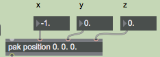
We have just changed the position attribute of the jit.gl.text3d object. The message can be followed by three number arguments that set the position of the object in three dimensions. If fewer than three numbers follow the position message, the axes are filled in the order [x, y, z], and the position of the object on the unspecified axes is set to 0. For example, sending the message . will set the position of a GL group object to the location [5, 0, 0].
The operation of changing an object’s position is called translation.
Now, let’s rotate the text.
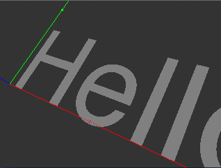
Sending the message followed by from one to four numbers sets the rotation attribute of an GL group object. The first number is an amount of rotation in degrees, counterclockwise around the object’s axis of rotation. The other three numbers specify this axis of rotation as an [x, y, z] vector. As with the attribute, some values following the rotation attribute can be dropped and default values will be understood. If the rotation message is followed by only one number, that number is understood to mean the angle in degrees, and the axis of rotation is [0, 0, 1]. This rotates the object around the z axis, or in other words, in the x-y plane of the screen. If two or more numbers accompany the rotation message, the first one always specifies the rotation angle, and following ones specify the vector of rotation in the order in which they appear.
Note that the red axis scales along with the object. The dots along the line are now twice as close together as they were before the scale operation. The axes are always drawn in the GL group’s local coordinate system, which in this case has been translated, rotated, and scaled with respect to the world coordinate system in the jit.gl.render object.
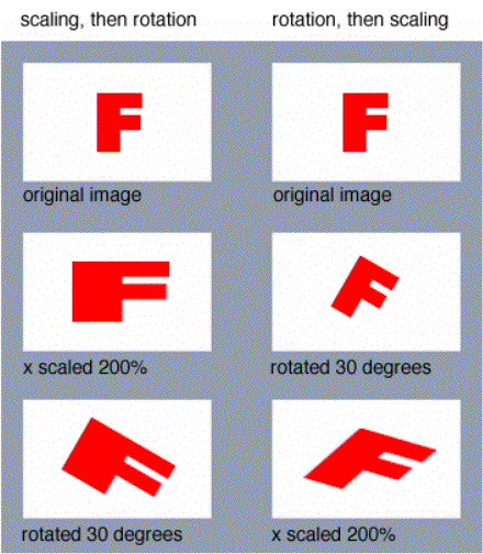
It's important to consider the order of operations when performing geometry transforms. You can set the rotate, position and scale attributes of an object independently in any order you wish. But each time it is drawn, the object is transformed in the following order:
- Scaling
- Rotation
- Translation
Keeping this order is essential so that the attributes behave predictably. If rotation occurred before scaling, for example, a message would scale the object not just in its x coordinate, but in some combination of x, y and z depending on the rotation of the object.
The following example shows the difference that performing operations in different orders makes.
Summary
Creating a draw context is the first step to using OpenGL graphics in Jitter. A draw context consists of a named destination, such as a window, and a jit.gl.render object drawing to that destination.
A variety of Jitter objects exist which draw OpenGL graphics in cooperation with jit.gl.render; their names all start with “jit.gl.” The jit.gl.text3d object is one example. All the Jitter OpenGL objects share a common set of attributes for moving them in 3D space. This group of objects is referred to as the GL group.
See Also
| Name | Description |
|---|---|
| Working with OpenGL | Working with OpenGL |
| jit.gl.model | Read and draw various 3D model formats |
| jit.gl.plato | Generate platonic solids |
| jit.gl.render | Render Jitter OpenGL objects |
| jit.gl.text3d | Render vector text |
| jit.window | Display data in a window |
| qmetro | Queue-based metronome |