Dynamics Tutorial 1: Envelope Following
In this group of tutorials, we'll look at different ways to work with dynamics in audio signals. The ability to use and control the amplitude of an audio waveform is important for many applications, from the macro level (audio compression) to the micro level (distortion). In this first tutorial, we'll learn to derive control values from amplitude parameters of an audio signal which we can use to control parameters elsewhere in the signal chain. This technique is called envelope following.
The envelope, please...
We've learned from working with MSP that digital audio is represented as a stream of discrete samples, each of which represent the amplitude of a signal at a given time. However, when we actually think about (and use) the term amplitude, we aren't necessarily thinking of it on a sample-by-sample basis. Instead, we discuss the amplitude of a sound based on how loud it seems to us as listeners. Alternately, we create objective measurement systems to attempt to quantify this (subjective) loudness, such as level meters in audio mixing software. Both of these systems look at the amplitude of an audio signal not on a sample-by-sample level, but averaged over time. This technique of deriving the macro-amplitude of a sound's loudness or volume (as opposed to the micro-amplitude of the sample values) is called envelope following.
We use the term envelope in synthesizer design to refer to the overall dynamic shape of the sound. For example, a sound that fades in smoothly and then fades out over the same amount of time could be said to have a triangular envelope. A sound with a short attack, a long sustain, and a short fade might look like a trapezoid. Similarly, we can take any sound source and, with a little bit of work, abstract its envelope:
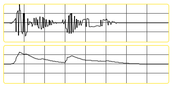
To create the envelope above, we looked at the samples within the waveform and tracked their average amplitude over time. There are several strategies to do this in MSP, involving a trio of objects that allow us to smooth audio signals based on different parameters.
Envelope following in MSP
The first thing that needs to be accomplished when deriving the smoothed amplitude of a sound is to convert the signal into a rectified wave; that is, to ignore the difference between negative and positive sample values and only concentrate on their distance from . We can do this by taking the absolute value of a signal, which can be accomplished using the abs~ object in MSP.
The snapshot~ object allows us to convert one sample of an MSP signal into a floating-point number output from the object as a Max event. Every time the object receives a , it takes the current audio sample and outputs it into Max as a number which can be viewed, scaled, or used to trigger Max events. In the case of our patcher, the absolute value of our groove~ object's output is being used to drive the height of a multislider object, with the snapshot~ providing the intermediary translation from an MSP signal t. a Max message. As we can see, the bouncing up and down of the multislider gives us a vague impression of the amplitude of the drum loop. However, a more accurate impression of how we hear the sound can be accomplished by smoothing those values.
The output of the send~ object (which consists of our drum loop) is converted to an absolute value, run through an object called rampsmooth~, and plotted in a number box and two multislider objects. The right-hand multislider is in one of its scrolling modes, which allows us to see values as they unfold over time. The rampsmooth~ object performs a linear smoothing operation on an input signal. Its two arguments (or numbers given at its middle and right inlets) control the way in which the smoothing behaves. The middle inlet controls over how many samples the object will smooth a changing value when it is rising; the right inlet controls how many samples it takes for a signal to fall. These two values allow us to independently smooth increasing and decreasing sample values, so that sharp onsets can be kept in the envelope but abrupt silences generate a tail.
The slide~ object smooths audio signals logarithmically. The two values provided work as denominators for new rising or falling energy entering the (smoothed) signal. For example, an 'Up' value of means it will take 1000 samples for a single-sample transition from to to occur. The larger the 'Up' and 'Down' values, the smoother the curve.
The deltaclip~ object works in a different manner from rampsmooth~ and slide~. It sets a threshold for the amount an audio signal can change, and clips the outgoing signal to that amount. Setting the and values for the delta to and will allow samples to pass normally provided they don't change by more than that amount. Smaller values will smooth the audio signal in a relative way so that the resulting envelope traces a much narrower set of values than the incoming signal.
If we put a burst of noise through the different envelope following techniques shown in our tutorial patcher, we can see the difference between the curves they generate:
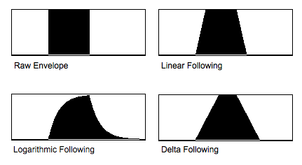
Each of these envelope-following techniques have different musical and sonic applications and have different signatures. A logarithmic envelope follower controlling the volume of a synthesizer, for example, would have a very different sound than a linear one.
Using envelopes as control signals
The three envelope following patcher areas send their output signals through send~ objects to any receive~ set to the appropriate name. In the case of patcher logic , this signal (ranging from to controls the frequency of a cycle~ object, mapping the control signal to between and Hz. The difference between the three envelope type should be apparent if they are set to fairly strong smoothing values.
In this example, we use our envelope control signal to modulate the cutoff frequency of a lores~ filter, creating a dynamic wah-wah effect on a mixed and detuned waveform.
In this example, we are using our envelope to create an 'auto-wah' on the drum loop itself. This is a very common use of envelope following in music production, where a control signal derived from an audio signal is used to control a parameter of an effect applied to that same audio clip further down the chain. Using this logic, we could use our envelope follower to produce control signals for any signal-processing procedure we want in MSP.
Summary
When talking about the amplitude of an audio signal, we distinguish between the sample-by-sample amplitude and the overall loudness of a sound. This second shape is called the envelope of a sound, and the signal processing involved in deriving it is called envelope following. Envelopes of audio signals can be created by looking at the absolute (rectified) waveform (created with the abs~) object and smoothing it using MSP objects such as rampsmooth~, slide~, or deltaclip~. These smoothed control signals can then be scaled and used to control parameters on any synthesis or signal processing operation you like. The MSP snapshot~ object is useful for converting MSP audio signals into floating-point Max numbers which can be viewed using objects such as multislider.
See Also
| Name | Description |
|---|---|
| Sound Processing Techniques | Sound Processing Techniques |
| abs~ | Absolute value of a signal |
| snapshot~ | Convert signal values to numbers |
| rampsmooth~ | Smooth an incoming signal |
| slide~ | Filter a signal logarithmically |
| deltaclip~ | Limit changes in signal amplitude |