MSP Analysis Tutorial 1: Signals and Meters
This chapter demonstrates several MSP objects for observing the numerical value of signals and translating those values into Max messages.
Display the value of a signal: number~
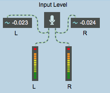
Every 250 milliseconds the number~ objects at the top of the Patcher display the current value of the signal coming in each channel, and the meter~ objects show a graphic representation of the peak amplitude value in the past 250 milliseconds, like an analog LED display.
The signal coming into number~ is sent out its right outlet as a once every time it's displayed. This means it is possible to sample the signal value and send it as a message to other Max objects.
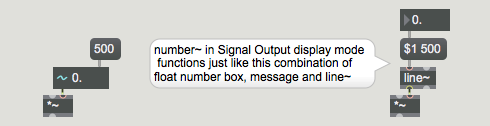
The number~ object is actually like two objects in one. In addition to receiving signal values and sending them out the right outlet as a , number~ also functions as a floating-point number box that sends a (instead of a ) out its left outlet.
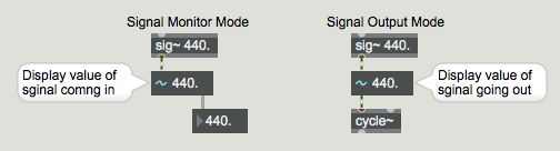
A number~ object simultaneously converts any signal it receives into s sent out the right outlet, and converts any it receives into a signal sent out the left outlet. Although it can perform both tasks at the same time, it can only display one value at a time. The value displayed by number~ depends on which display mode it is in. When a small waveform appears in the left part of the number~, it is inSignal Output Mode, and shows the value of the signal going out the left outlet.
You can restrict number~ to one display mode or the other by selecting the object in an unlocked Patcher and choosing Get Info... from the Object menu.
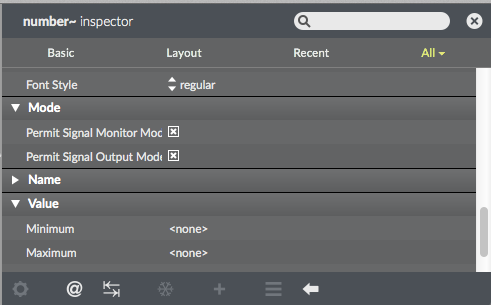
At least one display mode must be checked. By default, both display modes are allowed, as shown in the above example. If both display modes are allowed, you can switch from one display mode to the other in a locked Patcher by clicking on the left side of the number~. The output of number~ continues regardless of what display mode it's in.
In the tutorial patch you can see the two display modes of number~. The number~ objects at the top of the Patcher window are in Signal Monitor Mode because we are using them to show the value of the incoming signal. The ‘Amplitude’ number~ is in Signal Output Mode because we are using it to send a signal and we want to see the value of that signal. (New values can be entered into a number~ by typing or by dragging with the mouse only when it is in Signal Output display mode.) Since each of these number~ objects is serving only one function, each has been restricted to only one display mode in the Inspector window.
Interpolation with number~
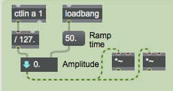
The number~ object has an additional useful feature. It can be made to interpolate between input values to generate a ramp signal much like the line~ object. If number~ receives a non-zero number in its right inlet, it uses that number as an amount of time, in milliseconds, to interpolate linearly to the new value whenever it receives a number in the left inlet. This is equivalent to sending a list to line~.
Unlike line~, however, number~ does not need to receive the interpolation time value more than once; it remembers the interpolation time and uses it for each new number received in the left inlet. This feature is used for the ‘Amplitude’ number~ so that it won't cause discontinuous changes of amplitude in the output signal.
Peak amplitude: meter~
The meter~ object periodically displays the peak amplitude it has received since the last display. At the same time it also sends the peak signal value out its outlet as a . The output value is always a positive number, even if the peak value was negative.
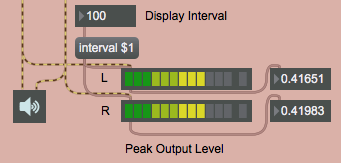
meter~ is useful for observing the peak amplitude of a signal (unlike number~, which displays and sends out the instantaneous amplitude of the signal). Since meter~ is intended for audio signals, it expects to receive a signal in the range -1 to 1. If that range is exceeded, meter~ displays a red ‘clipping’ LED as its maximum.
The default interval of time between the display updates of meter~ is 250 milliseconds, but the display interval can be altered with the message. A shorter display interval makes the LED display more accurate, while a longer interval gives you more time to read its visual and numerical output.
By the way, the display interval of a number~ object can be set in the same manner (as well as via its Inspector window).
Signal Probing
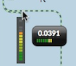
You don't have to include number~ and meter~ objects in your patch unless they are needed for the user interface. You can measure any audio signal at any time with the signal probe feature.
Now when audio is on you can point the mouse at an audio patchcord and see a balloon with a signal measurement and a meter display. This allows you to check the health of the signal anywhere in the patch.
Use a signal to generate Max messages: snapshot~
The snapshot~ object sends out the current value of a signal, as does the right inlet of number~. With snapshot~, though, you can turn the output on and off, or request output of a single value by sending it a . When you send a non-zero number in the right inlet, snapshot~ uses that number as a millisecond time interval, and begins periodically reporting the value of the signal in its left inlet. Sending in a time interval of stops snapshot~.
This right half of the tutorial patch shows a simple example of how a signal waveform might be used to generate MIDI data. We'll sample a sub-audio cosine wave to obtain pitch values for MIDI note messages.
Because snapshot~ is reporting the signal value every fifth of a second, and the period of the cycle~ object is about 7 seconds, the melody will describe one cycle of a sinusoidal wave every 35 notes. Since the amplitude of the wave is 0.5, the melody will range from 36 to 84 (60±24).
Amplitude modulation
The cycle~ object is modulating the amplitude of the incoming sound with a 4 Hz tremolo.
View a signal excerpt: capture~
The capture~ object is comparable to the Max object capture. It stores many signal values (the most recently received 4096 samples, by default), so that you can view an entire excerpt of a signal as text.
This object is useful for seeing precisely what has occurred in a signal over time. (4096 samples is about 93 milliseconds at a sampling rate of 44.1 kHz.) You can type in an argument to specify how many samples you want to view, and capture~ will store that many samples (assuming there is enough RAM available in Max. There are various arguments and messages for controlling exactly what will be stored by capture~. See its description in the MSP Reference Manual for details.
Summary
The capture~ object stores a short excerpt of a signal to be viewed as text. The meter~ object periodically displays the peak level of a signal and sends the peak level out its outlet as a . The snapshot~ object sends out a to report the current value of a signal. snapshot~ reports the signal value once when it receives a , and it can also report the signal value periodically if it receives a non-zero interval time in its right inlet.
The number~ object is like a combination of a number box, sig~, and snapshot~, all at once. A signal received in its left inlet is sent out the right outlet as a , as with snapshot~. A or received in its left inlet sets the value of the signal going out its left outlet, as with sig~. Both of these activities can go on at once in the same number~ object, although number~ can only display one value at a time. When number~ is in Signal Output Mode, it displays the value of the outgoing signal.
number~ can also function as a signal ramp generator, like the line~ object. If a non-zero number has been received in the right inlet (representing interpolation time in milliseconds), whenever number~ receives a , its output signal interpolates linearly between the old and new values.
These objects (along with a few others such as sig~floating-point number box and avg~) comprise the primary links between MSP and Max. They convert signals to numerical Max messages, or vice versa.
See Also
| Name | Description |
|---|---|
| Sound Processing Techniques | Sound Processing Techniques |
| capture~ | Store a signal to view as text |
| meter~ | Visual peak level indicator |
| number~ | Signal monitor and constant generator |
| snapshot~ | Convert signal values to numbers |