MSP interfaces with your computer's audio hardware via the dac~ and adc~ objects and their easy-to-use equivalents ezdac~ and ezadc~. If you don't have any special audio hardware and have no need for inter- application audio routing, the default driver on your system will give you stereo full- duplex audio I/O with no special configuration on your part.
In addition to Core Audio or MME on Windows, there are a number of other ways to get audio into and out of Max. Each of these methods involves using what we call a driver, which is actually a special type of Max object. Some of these drivers facilitate the use of MSP with third- party audio hardware. Also, a non real-time driver allows you to use MSP as a disk-based audio processing and synthesis system, removing the limit of how much processing you can do with your CPU in real time.
MSP audio driver objects are located in the ad folder located in the Resources/Externals folder inside the Max application folder. These object files must be in this folder (which stands for audio driver), otherwise MSP will be unable to locate them.
We will begin with a discussion of audio input/output in MSP in general. Later in this chapter we will discuss aspects of specific audio drivers that are available to you in MSP. First we'll discuss the Audio Status window and how to use it to get information about your audio hardware and set parameters for how MSP handles audio input and output.
The Audio Status Window
All global audio parameters in MSP are displayed in the Audio Status window. To open the Audio Status window, just double-click on any dac~ or adc~ object in a locked Patcher window. Alternately, you can choose Audio Status... from the Options menu.
The Audio Status window is arranged as a group of menus and checkboxes that set all of the parameters of the audio input and output in MSP. Since all of these options can be changed from within your patch, the Audio Status window serves as a monitor for your current audio settings as well.
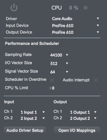
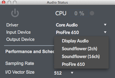
At the very top of the Audio Status window is a pop-up menu for turning the audio in MSP on and off and a set of pop-up menus that let you select an audio driver and configure its input source and output destination.
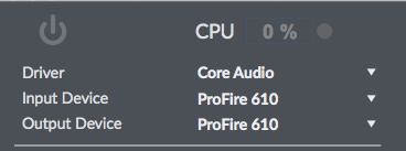
The second pop-up menu allows you to view and select an audio driver for MSP. The specific audio drivers will be discussed later in this chapter. A brief summary will suffice for now:
- : This setting shuts off MSP audio processing.
- : This is the default audio driver for MSP on Macintosh. It interfaces with the system's built-in Core Audio system and can be used with the built-in audio of the computer, or, with the proper software support, a third-party hardware interface, such as ASIO.
- , , or : (Windows only) On Windows, MSP loads the MME driver by default. If your sound card or external hardware supports DirectSound or WASAPI, they should also appear as an option on the pop-up menu.
- : This driver supports a standard developed by Propellerhead Software that allows sound generating applications (ReWire Devices) to send multiple channels of audio and midi to other applications (ReWire Mixers) that process and output it. Selecting the ad_rewire driver enables Max to function as a ReWire Device to route audio from MSP into applications that support ReWire (such as Live, Digital Performer or Cubase). Using MSP to host ReWire devices (such as Reason) can be accomplished with the rewire~ object.
- : (Windows only) If you have a third-party audio interface which supports ASIO (a cross-platform audio hardware standard developed by Steinberg), and it is installed correctly, it will be found by the MSP ASIO driver. You may have as many ASIO devices as you wish; they will all be found by the driver and will appear in the Driver pull-down menu in the Audio Status Window preceded by the word ASIO.
- : This driver enables MSP to work in non real-time mode, allowing you to synthesize and process audio without any real-time processor performance limitations. Real-time audio input and output are disabled under this driver.
Only one audio driver can be selected at any given time. MSP saves the settings for each audio driver separately and will recall the last used audio driver when you restart Max.
The next two pop-up menus are active only if the chosen driver and device support them. When they do the pop-up menus allow you to change the audio input source. These settings can also be changed using the Audio MIDI Setup application on Macintosh or the Sounds and Audio Devices Properties window (Start > Settings > Control Panel > Sounds and Audio Devices) on Windows.
When ASIO is in use, the pop-up menus allow you to set the clock source for your audio hardware and whether or not to prioritize MIDI input and output over audio I/O.
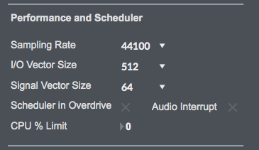
The Audio Status Window lets you control the size of the blocks of samples (called signal vectors) that MSP uses. There are two vector sizes you can control.
- The I/O Vector Size (I/O stands for input/output) controls the number of samples that are transferred to and from the audio interface at one time.
-
The Signal Vector Size sets the number of
samples that are calculated by MSP objects at one time. This can be less than or
equal to the I/O Vector Size, but not more. If the Signal Vector Size is less than
the I/O Vector Size, MSP calculates two or more signal vectors in succession for
each I/O vector that needs to be calculated.
With an I/O vector size of 256, and a sampling rate of 44.1 kHz, MSP calculates about 5.8 milliseconds of audio data at a time.
The I/O Vector Size may have an effect on latency and overall performance. A smaller vector size may reduce the inherent delay between audio input and audio output, because MSP has to perform calculations for a smaller chunk of time. On the other hand, there is an additional computational burden each time MSP prepares to calculate another vector (the next chunk of audio), so it is easier over-all for the processor to compute a larger vector. However, there is another side to this story. When MSP calculates a vector of audio, it does so in what is known as an interrupt. If MSP is running on your computer, whatever you happen to be doing (word processing, for example) is interrupted and an I/O vector's worth of audio is calculated and played. Then the computer returns to its normally scheduled program. If the vector size is large enough, the computer may get a bit behind and the audio output may start to click because the processing took longer than the computer expected. Reducing the I/O Vector Size may solve this problem, or it may not. On the other hand, if you try to generate too many interrupts, the computer will slow down trying to process them (saving what you are doing and starting another task is hard work). Therefore, you'll typically find the smaller I/O Vector Sizes consume a greater percentage of the computer's resources. Optimizing the performance of any particular signal network when you are close to the limit of your CPU's capability is a trial-and-error process. That's why MSP provides you with a choice of vector sizes.
Changing the vector sizes does not affect the actual quality of the audio itself, unlike changing the sampling rate, which affects the high frequency response. Changing the signal vector size won't have any effect on latency, and will have only a slight effect on overall performance (the larger the size, the more performance you can expect). However, certain types of algorithms benefit from a small signal vector size. For instance, the minimum delay you can get from MSP's delay line objects tapin~ and tapout~ is equal to the number of samples in one signal vector at the current sampling rate. With a signal vector size of 64 at 44.1 kHz sampling rate, this is 1.45 milliseconds, while at a signal vector size of 1024, it is 23.22 milliseconds. The Signal Vector size in MSP can be set as low as 2 samples, and in most cases can go as high as the largest available I/O Vector Size for your audio driver. However, if the I/O Vector Size is not a power of 2, the maximum signal vector size is the largest power of 2 that divides evenly into the I/O vector size.
You can set the audio sampling rate with the Sampling Rate pop-up menu. For full-range audio, the recommended sampling rate is 44.1 kHz. Using a lower rate will reduce the number of samples that MSP has to calculate, thus lightening your computer's burden, but it will also reduce the frequency range. If your computer is struggling at 44.1 kHz, you should try a lower rate.
The Max Scheduler in Overdrive option enables you to turn Max's Overdrive setting on and off from within the Audio Status window. When Overdrive is enabled, the Max event scheduler runs at interrupt level. The event scheduler does things like trigger the from a repeating metro object, as well as send out any recently received MIDI data. When it is not enabled, overdrive runs the event scheduler inside a lower-priority event handling loop that can be interrupted by doing things like pulling down a menu. You can also enable and disable Overdrive using the Options menu. Overdrive generally improves timing accuracy, but there may be exceptions, and some third-party software may not work properly when Overdrive is enabled.
The Scheduler in Audio Interrupt feature is available when Overdrive is enabled. It runs the Max event scheduler immediately before processing a signal vector's worth of audio. Enabling Scheduler in Audio Interrupt can greatly improve the timing of audio events that are triggered from control processes or external MIDI input. However, the improvement in timing can be directly related to your choice of I/O Vector Size, since this determines the interval at which events outside the scheduler (such as MIDI input and output) affect Max. When the Signal Vector Size is 512, the scheduler will run every 512 samples. At 44.1 kHz, this is every 11.61 milliseconds, which is just at the outer limits of timing acceptability. With smaller Signal Vector Sizes (256, 128, 64), the timing will sound ‘tighter.’ Since you can change all of these parameters as the music is playing, you can experiment to find acceptable combination of precision and performance.
If you are not doing anything where precise synchronization between the control and audio is important, leave Scheduler in Audio Interrupt unchecked. You'll get a bit more overall CPU performance for signal processing
DSP CPU Monitor
The DSP CPU Monitor window, found in the menu helps you monitor your system's performance.
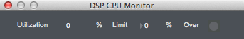
The CPU Utilization field displays a rough estimate of how much of your computer's CPU is being allocated for crunching audio in MSP. This also shows in Audio Status.
The CPU Limit option allows you to set a limit (expressed in terms of a percentage of your computer's CPU) to how much signal processing MSP is allowed to do. MSP will not go above the set CPU limit for a sustained period, allowing your computer to perform other tasks without MSP locking them out. The trade-off, however, is that you'll hear clicks in the audio output when the CPU goes over the specified limit. Setting this value to either 0 or 100 will disable CPU limiting.
The number next to Signals Used shows the number of internal buffers that were needed by MSP to connect the signal objects used in the current signal network. The number of Function Calls gives an approximate idea of how many calculations are being required for each sample of audio. Both of these fields will update whenever you change the number of audio objects or how they are patched together.
Vector Optimization only applies to PowerPC computers. Vector optimization allows four samples to be processed within the space of a single instruction. However, not all audio signal processing algorithms can be optimized in this way (for example, recursive filter algorithms are substantially immune from vector optimization). MSP itself no longer uses vector optimization, but third-party audio objects may still use it. In other words, unless you are using a vector-enabled third-party audio object on a PowerPC computer, this setting will have no effect.
The next portion of the Audio Status Window lets you map logical I/O channels.
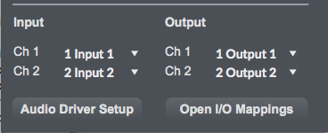
The pop-up menus labeled Input Channel 1, Input Channel 2, Output Channel Output Channel 2 allow you to map the first two logical channels of I/O in MSP (i.e. the first two outlets of the adc~ object and the first two inlets of the dac~ object) to physical channels used by your audiodriver. Different audio drivers give you different options, for example, the MME driver on Windows only supports two channels, so you will normally use the default options. To map additional logical channels, use the I/O Mappings window, which you can view by clicking the I/O Mappings button at the bottom of the Audio Status window (see below for more information about the I/O Mappings window). In addition, you can use the adstatus object from within your patch to map any of the 512 logical audio I/O channels.
About Logical Input and Output Channels
You can create a dac~ or adc~ object that uses a channel number between 1 and 512. These numbers refer to what we call logical channels and can be dynamically reassigned to physical device channels of a particular driver using either the Audio Status window, its I/O Mappings subwindow, or an adstatus object with an input or output keyword argument.
The adc~ and dac~ objects allow you to specify arguments which
define which logical channels are mapped to their inlets and outlets, respectively. In the
example below, multiple logical channels are in use in a simple patch:
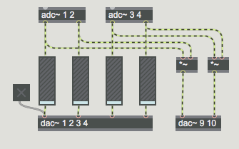
In this example, two separate adc~ objects output audio signals from logical channel pairs 1/2 and 3/4, respectively. The output of all four channels is sent to gain~ objects which attenuate the incoming signals and send them to the first four logical output channels, as specified by the first dac~ object. The input signals are also multiplied (ring modulated) and sent out logical channels 9 and 10. The ezadc~ and ezdac~ objects only access the first two logical input and output channels in MSP.
The purpose of having both logical channels and physical device channels is to allow you to create patches that use as many channels as you need without regard to the particular hardware configuration you're using. For instance, some audio interfaces use physical device channels 3 and 4 for S/PDIF input and output, others use channels 9 and 10 instead. Without logical mapping you would have to change the arguments on all of your adc~ and dac~ objects when you changed interfaces. With it, you can simply go to the Audio Status window and choose channel connections in the I/O Mapping window.
Logical channels in MSP are only created if there is a dac~ or adc~ object using them. In other words, if you're only using logical outputs 1 and 2, there aren't 510 unused audio streams sitting around hogging your CPU. However, since you can mix any number of logical channels to a single physical channel if necessary, you can create a complex multi-channel setup that will allow other people to hear all of your logical channels when they use it on a two-channel output device.
To assign multiple logical channels to one physical channel of an output device, use the I/O Mapping window. Click on the I/O Mappings button at the bottom of the Audio Status window.
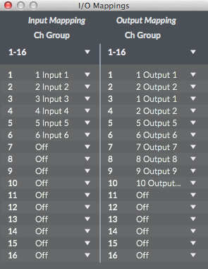
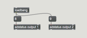
I/O Mappings are saved for each audio driver. You can also create I/O mappings within your patch using the adstatus object. The example patch below accomplishes the same remapping as that shown in the I/O Mapping window above, but does so automatically when the patch is loaded.
Using Core Audio
Core Audio provides audio I/O to Mac applications from both the computer's built-in audio hardware as well as any external audio hardware you may have.
If you have external audio hardware, it should come with the drivers to interface with Core Audio. When these drivers are installed and the hardware is present, Core Audio will include the external device as a Core Audio choice in the Driver menu in the Audio Status window.
The Sound part of the System Preferences application can be used to set basic sound settings for the system, such as the Output volume, left/right balance, and sound output device, as well as the Input volume and sound input device. You can also use the Audio MIDI Setup application (located in /Applications/Utilities) for more detailed control of the sound I/O settings. Note that modifications you make to the Sound section of the System Preferences application, such as changing the output volume or balance, are reflected in the audio MIDI Setup (and vice versa). You can open the Audio MIDI Setup application by clicking on the Open Audio Control Panel button in the lower left corner of the Audio Status Window in Max.
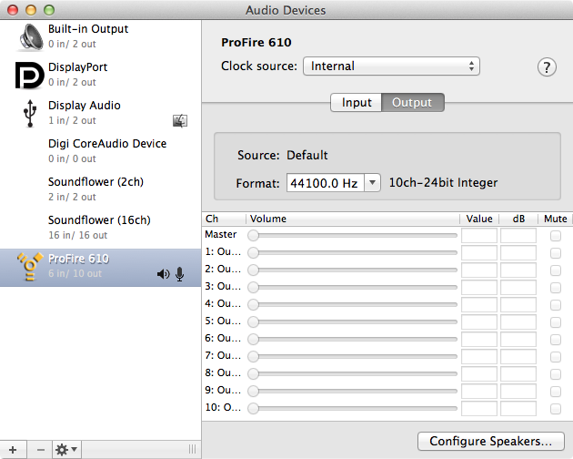
The right side of the audio window displays settings for the device selected on the left. The Input button allows you to select the Input Source (for example Line or Mic input for the selected device) as well as the sampling rate and bit depth in the Format pop-up menus. Similarly, the Output button allows you to select the sampling rate and bit-depth in its Format menus. The available selections will vary, depending on your audio hardware. Note that it is possible to set the sample rate for audio devices and Max differently, and Core Audio will handle the conversion. This conversion is not without its flaws however, so it is best to keep the same sample rate throughout the system.
When using external audio devices, the Input Volume and Output Volume sliders can be used to set the overall input and output volumes of the selected device (they are not available on all devices). The Mute checkboxes allow you to mute the input and output devices, if applicable.
Play Through is available only on some devices. The Thru checkbox to the right of each Input Volume slider lets you choose whether or not the input device is 'monitored' directly through to the output. When playthrough is enabled, the dry signal from the input source will play through to the output mixed in with any processed signal you may be sending to the output in MSP. Disabling playthrough will enable you to control how much (if any) dry signal from the audio input is routed to the output. Note that mixing input and output signals can produce problems due to delays associated with digital signal paths. Analog monitoring is almost always a better option.
This option can be changed in MSP by sending a message to the dsp object to change it. Put the following in a message box and clicking on it will turn playthrough off:
Using an argument of 1 will turn it on.
Some devices will allow the choice of Clock Source. If audio is coming in a digital input such as a S/PDIF connection, the sample clock must be precisely synchronized to the input data rate. Otherwise, there will be periodic clicks in the signal. On the other hand, if the chosen source for clock is turned off or disconnected, there will be no audio on any input.
The System Settings (gear icon) menu lets you choose which audio device is used for system audio input, output, and alerts. If a connected device has its own setup application, it can be acessed via the system settings menu.
Microsoft Drivers for Windows
Four types of sound card drivers are supported in Windows: MME, DirectSound, WASAPI, and ASIO. Your choice of driver will have a significant impact on the performance and latency you will experience with MSP.
The MME driver (ad_mme) is the default used for output of Windows system sounds, and will connect to almost any sound card and built-in audio system. While compatibility with your hardware is almost guaranteed, the poor latency values you get from an MME driver make this the least desirable option for real-time media operation.
DirectSound, built on Microsoft's DirectX technology, was the standard in XP. It provided much better latency and performance than MME drivers. If you are still running XP, a DirectSound driver (ad_directsound) should be used in preference to an MME driver. Occasionally, (and especially in the case of motherboard-based audio systems) you will find the DirectSound driver performs more poorly than the MME driver. This can happen when a hardware-specific DirectSound driver is not available, and the system is emulating DirectSound while using the MME driver. In these cases, it is best to use MME directly, or find an ASIO driver for your system.
Windows systems Vista and beyond provide WASAPI audio, which has lower latency than the legacy systems as well as 32 bit performance. WASAPI has two modes: shared and exclusive. In shared mode, audio from all open programs (including Windows sounds) will be output from the soundcard. Shared mode can handle differing sample rates and bit depths in programs and sound cards. In exclusive mode, MSP is directly connected to the soundcard- this gives the lowest latency possible. MSP and the sound card must be set to the same sample rate and bit depth, and of course, only one program at a time will have functioning audio. Max does not support exclusive mode, but if another application is using it, Max will not be able to access the sound card.
Most professional quality external audio interfaces will use ASIO drivers. The ASIO standard, developed by Steinberg, is optimized for very low latency and high performance. As with the DirectSound driver, you need to verify that performance is actually better than other options; occasionally, an ASIO driver will be a simple ‘wrapper’ around the MME or DirectSound driver, and will perform more poorly than expected.
Set up MME, DirectSound Drivers, or WASAPI with MSP on Windows
Finding a working audio driver on Windows is a process of elimination. First ensure your sound card or audio interface is running correctely with other applications. (If you have an ASIO card, jump down to Using ASIO on Windows.) Start with ad_portaudio Windows WASAPI as the driver. If that works, use it. If not, try ad_portaudio Windows DirectSound, then ad_portaudioMME. If all else fails, the ad_directsound and ad_mme drivers should get you something.
If an audio device only supports MME or DirectSound, the Windows OS does an automatic mapping of one to the other. Since many audio devices initially did not support DirectSound, Microsoft emulated DirectSound with a layer that bridged from DirectSound to MME. Currently, there is greater support for native DirectSound drivers, and sometimes when you use MME drivers Windows is actually running a layer to convert from MME to DirectSound.
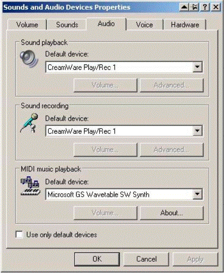
You can make overall changes to the basic operation of your default audio driver by accessing the Sounds and Audio Devices Properties window (Start > Settings > Control Panel > Sounds and Audio Devices). Here you can select Audio devices, and create settings for balance and output volume.
Input and Output Devices
When using MME, Directsound, or WASAPI drivers, you may choose input and output devices from the pull-down menus in the Max Audio Status window, which will be automatically populated with the drivers for your audio hardware. It is possible to use different audio devices for input and output simultaneously. However, this is not recommended or supported unless there is some external (from Max) provision for synchronizing the device's sample clocks. Devices internal to your computer will be synchronized, but external devices must share a common word clock.
Thread Priority and Latency Setting.
Both MME and Directsound drivers include settings for Thread Priority and Latency. These are both set by default to settings which we hope will work on your computer in the majority of situations. However, you may find that when you are working with a patch that you have problems which you may be able to resolve by changing some of these settings. If your audio is crackling or there are glitches in it, you may want to try increasing the latency setting. This has the disadvantage of making your audio feel less responsive in real time, but it will allow the audio driver more time to work on the extra audio demands you have placed on it.
If your system is slow in other areas -- such as screen redrawing or general timing accuracy -- you may wish to decrease the thread priority of the audio driver. This will give your other tasks more room to get done, but may also result in you needing to increase latency in order to give your audio driver room to breathe at the new lower priority.
Timing between the max scheduler and MSP is best when the I/O vector size is on the order of 1ms. We recommend setting the IO vector size to 128 samples. Having a setting of the latency separate from the I/O vector size allows this to work without audio glitches on most hardware.
Using ASIO on Windows
Selecting an ASIO driver from the Audio Status window allows MSP to talk directly to an ASIO audio interface. (Windows drivers feature several layers of software between program and hardware.) To use ASIO soundcards your device needs to be correctly installed and connected; The MSP ASIO driver will find it at startup.
All correctly installed ASIO devices should be available to you for selection in the Audio Status window. However, MSP does not check to see if the relevant audio interface hardware is installed correctly on your system until you explicitly switch to the ASIO driver for that interface card. If an ASIO driver fails to load when you try to use it, an error message will appear in the Max Console (typically, an initialization error with a code of –1000) and the menus in the rest of the Audio Status window will blank out. Switching to the MME and/or DirectSound driver will re-enable MSP audio.
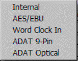
The Clock Source pop-up menu lets you to set the clock source for your audio hardware. Some ASIO drivers do not support an external clock; if this is the case there will only be one option in the menu, typically labeled Internal.
The Prioritize MIDI pop-up menu allows you to set the clock source for your audio hardware and whether or not to prioritize MIDI input and output over audio I/O.
Many ASIO drivers have other settings you can edit in a separate window. Click the Open ASIO Control Panel button at the bottom of the Audio Status window to access these settings. If your interface card has a control panel in its ASIO driver, the documentation for the interface should cover its operation.
Controlling ASIO Drivers with Messages to the dsp Object on Windows
Version 2 of the ASIO specification allows for direct monitoring of inputs to an audio interface. In other words, you can patch audio inputs to the interface directly to audio outputs without having the signals go through your computer. You also have control over channel patching, volume, and pan settings.
To control direct monitoring, you send the message to the dsp object. The message takes the following arguments
- Obligatory. A number specifying an input channel number (starting at 1)
- Optional. A number specifying an outlet channel number, or 0 to turn the routing for the specified input channel off. This is also what happens if the second argument is not present.
- or Optional. A number specifying the gain of the input -> output connection, between 0 and 4. 1 represents unity gain (and is the default).
- or Optional. A number specifying the panning of the output channel. -1 is left, 0 is center, and 1 is right. 0 is the default.
Patches input 1 to output 1 at unity gain with center pan.
Turns off input 1
patches input 1 to output 4 with 6dB gain panned to the left
Note: When using these messages, the word ‘driver’ is optional but recommended. Not all ASIO drivers support this feature. If you send the message and get an ASIO result error -998 message in the Max Console, then the driver does not support it.
Using ReWire with MSP
The ad_rewire driver allows you to use MSP as a ReWire Device, where MSP audio will be routed into a ReWire Mixer application such as Cubase. Both Max and the mixer application must be running at the same time in order to take advantage of ReWire's services. The mixer application should be also compatible with ReWire 2 or later for best results.
When the ad_rewire driver is selected, audio from MSP can be routed to any of 16 inter- application ReWire channels which will appear as inputs in ReWire mixer host applications. The first time ad_rewire is selected it will register itself with the ReWire system. Subsequent launches of ReWire Mixer applications will then offer Max as a ReWire device.
For example, after the Max ReWire Device is registered, Cubase will have a Max menu item in the Devices menu. When you choose it you will see a list of the audio outputs from Max. They will default to the off state. Click on any of the buttons to activate that channel. Once the channel is activated it will show up in the Cubase Track Mixer.
MSP can also be used as a Mixer Application for ReWire Devices such as Reason. To do this, you use the rewire~ object. Please see the MSP Reference Manual pages on the rewire~~ object for more information.
If you try to use rewire~and the ad_rewire audio driver simultaneously, you won't get any audio output. This is because each is waiting for the other: the ad_rewire driver is waiting for the rewire~ object to ask it for an audio stream, but the rewire~ object can't do anything unless given processing time by an audio driver.
However, you can use rewire~ in conjunction with a standalone built using Max when the standalone is using the ad_rewire driver.
Inter-application Synchronization and MIDI in ReWire
ReWire supports sending synchronization, transport, and tempo information both to and from ReWire Devices. The hostsync~, hostphasor~, and hostcontrol~ MSP objects can work with the ad_rewire driver to provide this information and to control the host's transport. See the MSP Reference Manual pages of these objects for more information.
Rewire 2 also supports MIDI communication to and from ReWire Devices. Currently both th. rewire~ object and the ad_rewire driver support MIDI, although they work in different ways. To send and receive midi using the rewire~ object, you send message to and receive messages directly from the object. See the MSP Reference Manual pages for the rewire~ object for more information.
The ad_rewire MIDI support is more integrated into the Max MIDI system -- Max MIDI ports are created so you can use the standard Max MIDI objects to send and receive MIDI via the ad_rewire driver. After you choose the ad_rewire driver in the Audio Status Window, MIDI ports will appear in the MIDI Setup window the next time it is opened. The number of midi ports dedicated to ReWire can be changed using the MIDI Ports option in the Audio Status Window.
For example, you can choose one of the Max ReWire MIDI ports as a MIDI output device in Cubase and then use standard Max MIDI objects (such as notein) to control your Max created synthesizer. Likewise, you can send MIDI into Cubase using the max MIDI objects and the ReWire MIDI ports, and recorded the results to a track for further manipulation or playback.
Advanced ad_rewire Features
When you build a standalone application using Max you can use the ad_rewire driver in your standalone and it will create an ReWire Device that works independently of Max and other Max-created standalone applications. By default, the ReWire Device will take on the name of your application and will have 16 channels. You can customize this by editing the msprewire.config file in the support/ad folder for your standalone. Note: This file doesn't exist until the default one is created the first time you launch your standalone and choose ad_rewire in the Audio Status window.
The msprewire.config file is located in the ad folder found in the following locations:
Macintosh. Library/Application Support/Cycling '74/ad/
Windows: c:\Program Files\Cycling '74\Max 7\Cycling '74\ad
In a Max-built standalone this is in the standalone's support/ad/ folder. The msprewire.config contains two lines that specify the name that ReWire will use for the device and the number of audio channels. You can edit this to change the behavior of Max or your standalone.
Working in Non-Real Time with MSP
The MSP NonRealTime driver allows you to use MSP for synthesis and signal processing without worrying about the constraints imposed by the speed of your computer's CPU. Non-real-time mode simply calculates samples in MSP independently of any physical scheduling priority, allowing you to process a vector of audio using a signal path that might take your computer more than one vector's worth of real time to compute.
Typically, you will want to use the dsptime~ object to see how long the audio has been turned on, and you will pipe the output of your routine to sfrecord~ to capture the results. Hardware audio input and output under the non-real-time driver are disabled.
A typical non-real-time signal path in MSP would look something like this:
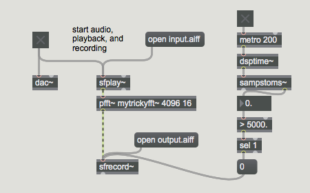
Starting the Audio (by toggling the dac~ object) will start the dsptime~ object at 0 samples, in sync with the playback of the audio out of sfplay~ and the recording of audio into the sfrecord~ at the bottom of the patch. When five seconds have elapsed, the sfrecord~ object will stop recording the output audio file.
See Also
| Name | Description |
|---|---|
| adc~ | Audio input and on/off |
| adstatus | Report and control audio driver settings |
| dac~ | Audio output and on/off |
| ezadc~ | Audio input and on/off button |
| ezdac~ | Audio output and on/off button |