Tutorial 41: Shaders
One of the primary purposes of graphics cards is to render 3D objects to a 2D frame buffer to display. How the object is rendered is determined by what is called the "shading model", which is typically fed information such as the object's color and position, lighting color and positions, texture coordinates, and material characteristics like how shiny or matte the object should appear. The program that executes in hardware or software to perform this calculation is called the shader. Traditionally graphics cards have used a fixed shading pipeline for applying a shading model to an object, but in recent years, graphics cards have acquired programmable pipelines so that custom shaders can be executed in place of the fixed pipeline. For a summary off many of the ways to control the fixed OpenGL pipeline, see Tutorial 35: Lighting and Fog.
Hardware Requirement: To fully experience this Tutorial, you will need a graphics card that supports programmable shaders, e.g. ATI Radeon 9200, NVIDIA GeForce 5000 series or later graphics cards. It is also recommended that you update your OpenGL driver with the latest available for your graphics card. On Macintosh, this is provided with the latest OS update. On PC, you can acquire the latest driver from either your graphics card manufacturer or your computer manufacturer.
Flat Shading
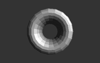
One of the simplest shading models which takes lighting into account is called Flat Shading or Facet Shading, where each polygon has a single color across the entire polygon based on surface normal and lighting properties. As we saw demonstrated in Tutorial 35, this can be accomplished in Jitter by setting the lighting_enable attribute of a Jitter OpenGL object (e.g. jit.gl.gridshape) to 1.
Getting Started
-
Open the Tutorial patch 41jShaders in the Jitter Tutorial folder. Click on the toggle box labeled Start Rendering.
-
Click the toggle box object above the message box object reading
lighting_enable $1to turn on lighting for the jit.gl.gridshape object drawing the torus. Thesmooth_shadingattribute is0by default. -
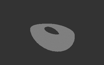
Now you should see a change in the lighting of the torus. Instead of the dull gray appearance it started with, you will see a shiny gray appearance like this:
Smooth Shading
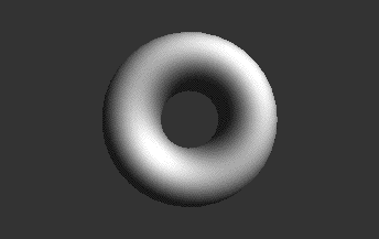
While this might be a desirable look, the color of most objects in the real world changes smoothly across the surface. "Gouraud Shading" (1971) was one of the first shading models to efficiently address this problem by calculating a per vertex color based on surface normal and lighting properties. It then linearly interpolates color across the polygon for a smooth shading look. While the artifacts of this simple approach might look odd when using a small number of polygons to represent a surface, when using a large number of polygons, the visible artifacts of this approach are minimal. Due to the computational efficiency of this shading model, Gouraud Shading has been quite popular and remains the primary shading model used today by computer graphics cards in their standard fixed shading pipeline. In Jitter, this can be accomplished by setting the smooth_shading attribute to 1 (on). Let's do this in our patch, increasing and decreasing the polygon count by changing the dim attribute of the jit.gl.gridshape object.
- Click the toggle box attached to the message box reading
smooth_shading $1. Try increasing and decreasing the polygon count by changing the number box attached to the message box readingdim $1 $1in the lower right of the patch.
Per-Pixel Lighting
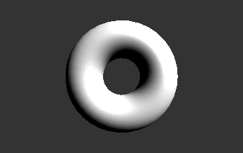
As mentioned, smooth shading with a low number of polygons has visible artifacts that result from just performing the lighting calculation on a per vertex basis, interpolating the color across the polygon. Phong Shading (1975) smooths not only vertex color across a polygon, but also smooths the surface normals for each vertex across the polygon, calculating a per fragment (or pixel) color based on the smoothed normal and lighting parameters. The calculation of lighing values on a per pixel basis is called "Per Pixel lighting". This is computationally more expensive than Gouraud shading but yields better results with fewer polygons. Per pixel shading isn't in the OpenGL fixed pipeline; however we can load a custom shader into the programmable pipeline to apply this shading model to our object.
-
Load the per-pixel lighting shader by clicking the message box that says
read mat.dirperpixel.jxsconnected to the jit.gl.shader object. -
Apply the shader to our object by clicking the message box
shader shademeconnected to the jit.gl.gridshape object. This sets object’sshaderattribute to reference the jit.gl.shader object by itsname(shademe).
Programmable Shaders
In 1984, Robert Cook proposed the concept of a shade tree, where one could build arbitrary shading models out of some fundamental primitives using a "shading language". This shading language made it so that a rendering pipeline could be extended to support an infinite number of shaders rather than a handful of predefined ones. Cook's shading language was extended by Ken Perlin to contain control structures and became the model used by Pixar's popular RenderMan shading language. More recently the GPU-focused Cg and GLSL shading languages were established based on similar principles. The custom shaders used in this tutorial, including the per-pixel lighting calculation, were written in GLSL.
A brief introduction to how to write your own shaders will be covered in a subsequent Tutorial. For now, lets continue to use pre-existing shaders and show how we can dynamically change shader parameters. Gooch shading is a non-photorealistic shading model developed primarily for technical illustration. It outlines the object and uses warm and cool colors to give the sense of depth desired for technical illustrations. We have a custom shader that implements a simplified version of Gooch Shading which ignores the application of outlines.
- Load the simplified Gooch shader by clicking the message box
read mat.gooch.jxsconnected to the jit.gl.shader object.
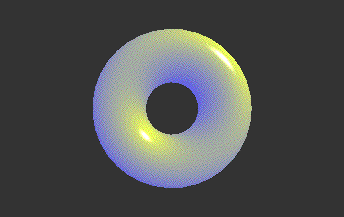
You should notice that the warm tone is a yellow color and the cool tone is a blue color. These values have been defined as defaults in our shader file, but are exposed as parameters that can be overridden by messages to the jit.gl.shader object.
- Using the number boxes in the patch, send the messages
param warmcolor <red> <blue> <green> <alpha>andparam coolcolor <red> <green> <blue> <alpha>to the jit.gl.shader object to change the tones used for the warm and cool colors.
We can determine parameters available to the shader by sending the jit.gl.shader object the message dump params to print the parameters in the Max Console, or by sending the message getparamlist, which will output a parameter list out the object’s rightmost (dump) outlet. An individual parameter's current value can be queried with the message getparamval <parameter-name>. A parameter’s default value can be queried with the message getparamdefault <parameter-name>, and the parameter’s type can be queried with getparamtype <parameter-name>.
Vertex Programs
Shaders can be used not only to determine the surface color of objects, but also the position and attributes of our object's vertices, and as we'll see in our next Tutorials. For now, let's look at vertex processing. In the previous shaders we just discussed how the different shaders would render to pixels. In fact, for each of these examples we were running two programs: one to process the vertices (the vertex program) and one to render the pixels (the fragment program). The vertex program is necessary to transform the object in 3D space (rotation, translation, scaling), as well as calculate per-vertex lighting, color, and other attributes. Since we see the object move and rotate as we make use of the jit.gl.handle object in our patch, obviously some vertex program must be running. Logically, the vertex program runs on the programmable vertex processor and the fragment program runs on the programmable fragment processor. This model fits with the fixed function pipeline that also separates vertex and fragment processing tasks.
The custom vertex program in the previous examples, however, didn’t visibly perform any operation that is noticeably different than the fixed pipeline vertex program. So let’s load a vertex shader that has a more dramatic effect. The vd.gravity.jxs shader can push and pull geometry based on the vertex distance from a point in 3D space.
-
Load the simplified gravity vertex displacement shader by clicking the message box
read vd.gravity.jxsconnected to the jit.gl.shader object. -
Control the position and amount of the gravity vertex displacement shader by changing the number boxes connected to the pak object and message box outputting the messages
param gravpos <x> <y> <z>andparam amount <n>, respectively.
Summary
In this tutorial we discussed the fixed and programmable pipelines available on the graphics card and demonstrated how we can use the programmable pipeline by loading custom shaders with the jit.gl.shader object. Shaders can then be applied them 3D objects to obtain different effects. We can also set and query shader parameters through messages to the jit.gl.shader object.