Tutorial 32: Camera View
This tutorial shows you how to set up the camera view and how to position and rotate GL objects using jit.gl.handle. It will cover the group of components which together make up the camera view: the camera's position, the point at which the camera is looking, the "up" vector, the type of projection, the lens angle, and the clipping planes.
In the lower left of the patch, there is a jit.window object named . This window will be the destination for our OpenGL drawing. You will notice that the jit.window object has an attribute argument to specify the creation of a depth buffer. A depth buffer allows the OpenGL renderer to determine which drawing command is visible at a given pixel based on the proximity of the geometry to the camera. Without depth buffering, OpenGL uses what is often referred to as the "Painter's Algorithm"--i.e. the visible results of drawing commands correspond to sequence in which they are performed.
• Click on the toggle object labeled Start Rendering.
We now see large gray circle and some yellow lines. These are being drawn by two instances of the jit.gl.gridshape object. The jit.gl.gridshape object can draw a variety of 3D shapes, including spheres, tori, cylinders, cubes, planes, and circles. The grey circle we see drawn in the window is actually a sphere and is being drawn by section of the patch labeled Grey Shape. The yellow lines are actually a plane and are being drawn by the section of the patch labeled Yellow Plane. The yellow plane is being rendered with which means that the shape is being drawn with outlined polygons rather than filled polygons for both the front and back faces of the plane. If you switch off the toggle object connected to the message box , you can see the plane rendered with filled polygons.
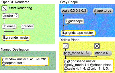
• In the Grey Shape section of the patch, click on the message box and then click on the message box containing . You should now see what looks like a grey doughnut.
• Click on the toggle object connected to the message box and then click on the toggle object connected to the message box . We are now staring at a lit, smoothly shaded, 3D gray torus.
By default, Jitter's GL objects have lighting and smooth shading disabled, so it is necessary to turn these on. Lighting will be covered in detail in Tutorial 36.
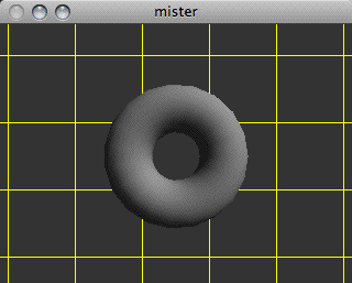
• In the Camera View section of the patch, click on the toggle object jit.gl.render axes.
You should see a red line from the center of the window to the right of the window, a green line from the center of the window to the top of the window. These are the x and y axes, respectively. They help us to determine the origin of our scene. Since the default camera position is at [0.,0.,2.], and the default position is [0.,0.,0.], the camera is looking directly at the origin of our scene along the z axis. Hence, we do not see the blue line which represents the z axis along which the camera is looking.
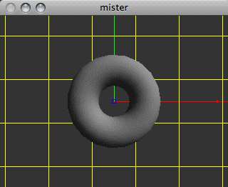
• Under the camera position label, set the x value to be . Now the camera is at the position [1.,0.,2.], it is still looking at the position [0.,0.,0.], and the blue line of the z axis has become visible.
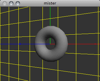
• Now let's set the x value to y value to - and z value to . so that the camera position is [6,–6,6]. You can see that the yellow plane and the axes are, in fact, finite.
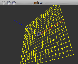
So far, the y axis has always been pointing upwards with respect to the camera view. This is because the default "up" vector is [0.,1.,0.]—i.e. the unit y vector.
• Under the up vector label, let's set the y value to 0. and the z value to 1. We see that the view has rotated, and the blue line of the z axis is now pointing upwards.
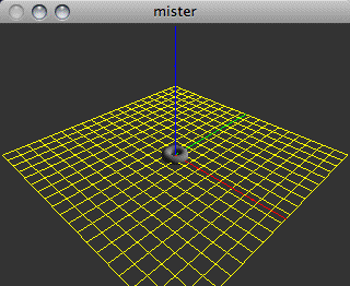
You may have noticed, as we've moved the camera further away from the origin, that the torus, plane, and axes have become smaller. This is because the default viewing mode uses a perspective projection, which is similar to the way we see things in the 3-dimensional world we inhabit. If you are familiar with camera lenses, you may also know that depending upon the angle of the lens, objects will be smaller as the lens angle increases to accommodate a larger field of view. Similarly, we can change the lens angle of our perspective transformation to increase the field of view, and in doing so the objects will become yet smaller.
• The default lens angle is 45 degrees, so let's change it to something like 60 degrees by changing the number box connected to the message box .
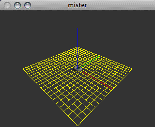
Another type of projection supported by OpenGL is the orthographic projection. This type of projection does not diminish the size of objects based on camera position. The orthographic projection is common to 3D CAD software used for tasks such as mechanical engineering. Many early video games like Q-Bert also used an orthographic projection. You can switch between the perspective projection and the orthographic projection by clicking on the toggle box labeled orthographic projection. The message will turn on orthographic projection. If you try moving the camera with orthographic projection turned on, you should not see the objects become any smaller. However, changing the lens angle will still change the field of view, and the size of objects relative to the view.

• Click on the toggle again to turn off the orthographic projection with an message.
Let's examine the clipping planes that determine the extent along the camera's view that will be rendered. OpenGL has a near clipping plane and a far clipping plane, and only geometry which lies in between these two planes will be rendered. These clipping planes are specified in units of distance from the camera along the viewing vector using the and messages. By default, the near clipping plane is set to 0.1 and the far clipping plane is set to 100.
• Try increasing the near clipping plane to and decreasing the far clipping plane to You should see the near and far edges of the yellow plane that fall outside the clipping planes disappear.
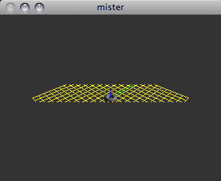
• Set the near clipping plane back to the default of and the far clipping plane back to the default of .
So far, the camera has always been looking at the origin [0.,0.,0.]. If we change the position's x value to , the camera is now looking at [3.,0.,0.].
• Let's move the torus to the position [3.,0.,0.], by clicking on the message box containing . in the section of the patch labeled UI Rotation and Position Control. The torus is now again located at the center point of the view, [3.,0.,0.].

Not only did this send the message to the torus, but also to the jit.gl.handle object. The jit.gl.handle object is a GL group object that uses mouse information to move and rotate objects in the 3D scene. Like the jit.gl.gridshape object, the jit.gl.handle object requires a named draw context into which to draw. Unlike the jit.gl.gridshape object, it's also a user interface object that translates mouse activity in the draw context's destination to Max messages.
In this patch, messages from the jit.gl.handle object are sent to the jit.gl.gridshape object. They are also sent to the route object and formatted so you can see exactly what is being sent. These messages are the only communication from the jit.gl.handle object—there is nothing going on "behind the scenes."
If you click on the torus and drag the mouse, you will see the torus being rotated by the jit.gl.handle object as though it were a virtual trackball. If you hold down the command key while dragging, you can move the torus left, right, up, and down. If you hold the option key as you drag, you can move the torus towards you or away from you. Using the shift key as you perform any of the above mouse actions will constrain the action to a single axis.
• Try manipulating the orientation of the torus by clicking on it in the jit.window object. Get a feel for how the jit.gl.handle object translates the 2-dimensional mouse information into 3-dimensional rotation information.
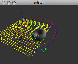
As with the displayable axes of the jit.gl.render object, the jit.gl.handle object shows colored lines that correspond to the x (red), y (green), and z (blue) planes of the object being rotated. The lines appear as circles around the relevant object being "handled." The mouse controls the axes whose circles are nearest to the front of your current field of view. By manipulating the image so that those circles move to the back of the object, you can control a different pair of axes with the next mouse click. The modifier keys let you reposition the object by relocating it on the three axes. The jit.gl.handle object outputs the relevant messages to set the and attributes of the GL group object attached to it. Note that if you are displaying a GL context in a jit.pwindow, the Help in Locked Patchers option of Max (which you can change under the Options menu) needs to be disabled in order for zooming to work using jit.gl.handle. Otherwise, the option key will cause the help patch for jit.pwindow to appear(!).
Summary
We have examined the several components which make up an OpenGL scene's camera view, and the necessary attributes of the jit.gl.render object which control them. The attribute specifies the camera position; specifies the upwards vector; specifies the position at which the camera is looking; specifies whether to use an orthographic or perspective projection; and and specify the clipping planes. Lighting and smooth shading attributes can be enabled by setting the and attributes of the GL group object handling the geometry (in this case the jit.gl.gridshape object).
The jit.gl.handle object lets us rotate and reposition OpenGL objects using the mouse and the modifier keys on the keyboard. The jit.gl.handle object takes the name of a valid draw context to attach itself to, and sends messages to any connected object that is also using that context, setting the and attributes of that object.
See Also
| Name | Description |
|---|---|
| jit.gl.gridshape | Generate simple geometric shapes as a connected grid |
| jit.gl.handle | Use mouse movement to control position/rotation |
| jit.gl.render | Render Open GL |
| jit.window | Display data in a Window |