Tutorial 35: Lighting and Fog
Note: Some techniques described in this tutorial are outdated. Users are recommended to use the jit.gl.light and jit.gl.material objects to adjust lighting and material properties of 3D objects.
Lighting—the illumination of objects in the real world—is a very complex subject. When we view objects, our eyes focus and detect photons throughout a range of energies that we call visible light. Between their origin in the Sun, lightning, fireflies or other light sources and our eyes, they can travel on a multitude of complex paths as they are reflected from or refracted through different materials, or scattered by the atmosphere. Our computers won’t be dealing with this level of complexity anytime soon, so OpenGL simplifies it greatly.
The OpenGL Lighting Model
Lighting in OpenGL is based on a very rough model of what happens in the real world. Though very crude compared to the subtlety of nature, it is a good compromise, given today’s technology, between the desire for realism and the cost of complexity.
We have already seen how colors in OpenGL are described as RGB (red, green and blue) values. The lighting model in OpenGL extends this idea to allow the specification of light in terms of various independent components, each described as RGB triples. Each component describes how light that’s been scattered in a certain way is colored. The continuum of possible real-world paths is simplified into four components, listed here from most directional to least directional.
The specular light component is light that comes from a certain direction, and which also reflects off of surfaces primarily in a given direction. Shiny materials have a predominant specular component. A focused beam of light bouncing off of a mirror would be a situation where the specular component dominates.
Diffuse light comes from one direction, but scatters equally in all directions as it bounces off of a surface. If the surface is facing directly at the light source, the light radiation it receives from the source will be the greatest, and so the diffuse component reflected from the surface will be brightest. If the surface is pointing in another direction, it will present a smaller cross-section towards the light source, and so the diffuse component will be smaller.
Ambient light is direction-less. It is light that has been scattered so much that its source direction is indeterminate. So it appears equally bright from all directions. A room with white walls would be an environment with a high ambient lighting component, because so many photons bounce from wall to wall, scattering as they do so, before reaching your eye.
Finally, emissive lighting is another component that doesn’t really fall anywhere on the directionality scale. It is light that only reaches your eye if you’re looking directly at the object. This is used for modeling objects that are light sources themselves.
These components are used to describe materials and light sources. Materials made of specular, diffuse, ambient and emissive components are applied to polygons to determine how they will be colored. Polygons with materials applied are lit based on their positions and rotations relative to light sources and the camera, and the specular and diffuse properties of light sources, as well as the ambient light component of the scene.
Getting Started
-
Open the tutorial patch. Click on the toggle (in the lower left, this time) labeled Start Rendering.
-
Click the message box reading
name lt, depthbuffer 1above the jit.pwindow object. This creates a depth buffer so that hidden-surface removal can be done.
You will see a flat gray torus and a small white circle in the jit.pwindow object. The jit.gl.gridshape object in the center of the tutorial patch draws the torus. The other jit.gl.gridshape object in the patch, towards the right, draws the white circle. The scene is all presented in flat shades because lighting is not yet enabled.
- Click the toggle box objects above the top three message box objects reading
lighting_enable $1,smooth_shading $1, andauto_material $1to set those attributes of the jit.gl.gridshape object drawing the torus to1.
Lighting is off by default for each object, so you must enable it. The same goes for smooth shading. When you set these two attributes, you will see the torus go through the now-familiar progression (assuming you’ve been doing these tutorials in order) from flat shaded to solid faceted to solid and smooth. When you set the auto_material attribute to 1, you won’t see any change, because its default value is already 1.
-
Click the toggle objects above the message box labeled
auto_material $1again, to set theauto_materialattribute of the jit.gl.gridshape object to0. -
Now you should see a change in the lighting of the torus. Instead of the dull gray appearance it started with, you will see a shiny gray appearance like this:
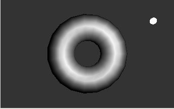
The auto_material attribute is provided in Jitter so that you don’t always need to specify all the components of a material just to see an object lit. When the auto_material attribute of an object in the GL group is on and lighting is enabled for the object, the diffuse and ambient material components for the object will be set to the object’s color, and the specular and emissive lighting components are disabled. This resulted in the flat gray torus we saw initially. In this tutorial, though, we want to see what happens when all the lighting components are specified explicitly, so we have turned the auto_material attribute off.
The image that results appears shinier, because the material applied to the torus now has a specular component.
Moving the Light
The jit.gl.gridshape object drawing the white circle has a jit.gl.handle object attached to it. As we’ve seen before this allows you to move the circle by clicking and dragging over it with the command key held down. By dragging with the option key held down, you can move the circle towards and away from the camera in the scene.
The x, y and z position values from the jit.gl.handle object are also routed to an unpack object, which sends them to number box objects for viewing. A pak object adds the symbol light_position to the beginning and another value to the end of the list. This message is sent to the jit.gl.render object to set the position of the light in the scene. Note that the light itself is not visible, except in its effect on other objects. The white circle is a marker we can use to see the light’s position.
- Click and drag the white circle with the command key held down to move it to the lower left corner of the scene. Then drag with the option key held down to move it away from the camera.
The light source moves with the white circle. If you move it to the right place, you can create an image like this.
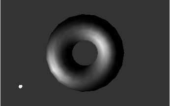
The diffuse and specular components of the light are combined with the diffuse and specular components of the material at each vertex, according to the position of the light and the angle at which the light reflects toward the camera position. When you move the light, these relative positions change, so each vertex takes on a different color.
Normals: For lighting to take place, each vertex of a model must have a normal associated with it. The normal is a vector that is defined to be perpendicular to the surface of the object at the vertex. This is the value used to determine the contribution of the specular and diffuse lighting components to the image. Creating reasonable normals for a complex object can be a time-consuming process.Jitter attempts to prevent you from worrying about this as much as possible, in a couple of ways. First, most objects in the GL group have normals associated with them. These are calculated by the object that does the drawing. The jit.gl.gridshape object is one example. If its shape is set to a sphere, it generates a normal at each vertex pointing outwards from the center of the sphere. Each shape has a different method of calculating normals, so that the surfaces of the various shapes are smooth where curved, yet the edges of shapes like the cube remain distinct and unsmoothed.Secondly, if you send geometries directly to the jit.gl.render object in matrices, the jit.gl.render object will automatically create normals for you to the best of its ability. If you draw a connected grid geometry by sending a matrix followed by the tri_grid or quad_grid primitives, the generated normals will be smoothed across the surface of the grid. If you send a matrix using other primitives such as triangles, jit.gl.render will make no attempt to smooth the vertices, but will generate a normal for each distinct polygon in the geometry. If you want to make your own normals, you can turn automatic normal generation off with by setting the attribute auto_normals of the jit.gl.render object to 0.
Tutorial 37, "Geometry Under the Hood" describes how vertices, colors and normals can be passed in Jitter matrices to the jit.gl.render object. For more information on how to specify normals for geometry within a matrix, please refer to the Jitter Appendix B in this publication.
Specular Lighting
Let’s change the specular components of the lighting to get a better feel for them.
- Locate the swatch object above the prepend
mat_specularobject. Move the circle in the swatch to the far left, centered vertically. This sends themat_specularmessage to the jit.gl.gridshape object, followed by RGB color values that describe a pure red color.
The swatch object sends it output as a list of three integers from 0 to 255. The vexpr object divides each integer in the list by 255. to generate a floating-point value in the range 0. to 1. , which is the range Jitter’s OpenGL objects use to specify colors.

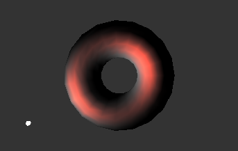
The highlights of the image now have a red color. The specular component of the light source, which is currently white, is multiplied by the specular material component to produce the color of the highlights.
The red, green and blue values of the specular light source are multiplied by the red, green and blue values of the specular material component, respectively. So if the light source component and the material component are of different colors, it’s possible that the result will be zero, and no highlights will be generated. This more or less models the real-world behavior of lights and materials: if you view a green object in a room with red light, the object will appear black.
- Try moving the circle in the swatch object above the prepend
light_specularobject to a green color. The highlights will disappear. Different colors with varying amounts of red will produce different brightnesses of red. When you are done, move the circle to the top of the swatch object so that the highlights are red again.
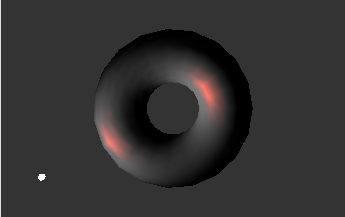
The shininess attribute of objects in the GL group is an important part of the material definition. It specifies to what extent light is diffused, or spread out, when it bounces off of the object. To model a mirror, you would use a very high shininess value. Values of approximately 2 to 50 are useful for making realistic objects.
This makes the contribution of the specular lighting components much smaller in area. Accordingly, you can see the specular lighting in red quite distinctly from the diffuse lighting, which is still gray.
Diffuse Lighting
Let’s manipulate the colors some more to see the effect of the diffuse component.
- Locate the swatch object above the prepend
mat_diffuseobject. Move the circle in the swatch approximately to the location in the illustration below, to produce a deep blue diffuse material component.

The diffuse reflections from the torus are now blue, and the highlights are magenta. This is because the color components of an object’s material, after being multiplied with the lighting components depending on positions, are added together to produce the final color for the object at each vertex.
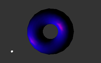
Ambient Lighting
We have yet to change the ambient component of the object’s material. Currently, this is set to its default of medium gray, which is multiplied by the dark gray of the global ambient component to produce the dark gray areas of the torus in the picture above. The global ambient component is multiplied by all ambient material components in a scene, and added to each vertex of each object. You can set this with the light_global_ambient attribute of the jit.gl.render object.
- Set the circle in the swatch object above the prepend
mat_ambientto a green color to produce a green ambient material component.
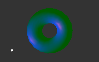
The ambient material component is multiplied by the global ambient illumination component to make the dark green areas that have replaced the gray ones.
The moveable light in the scene has an ambient component associated with it, which is added to the global ambient component. To change this, you can move the circle in the swatch object above the prependlight_ambient object. If you change this to a bright color, the whole object takes on a washed out appearance as the intensity of the ambient component gets higher than that of the diffuse component.
That’s Ugly!
A green torus with blue diffuse lighting and magenta highlights is probably not something you want to look at for very long. If you haven’t already, now might be a good time to play with the color swatches and come up with a more harmonious combination.
Note that control over saturation isn’t provided in this patch for reasons of space. But it’s certainly possible to specify less saturated colors for all the lighting and material components.
Directional vs. Positional Lighting
The moveable light in a scene can be either directional or positional. In the message light_position [x] [y] [z] [w] sent to jit.gl.render, the value [w] decides whether directional or positional lighting is used. If [w] is zero, the light is a directional one, which means that the values [x], [y] and [z] specify a direction vector from which the light is defined to come. If [w] is nonzero, the light is a positional one—it illuminates objects based on its particular location in the scene. The position of the light is specified by the homogeneous coordinates [x]/ [w], [y] /[w] and [z]/ [w].
Positional lights are good for simulating artificial light sources within the scene. Directional lights typically stand in for the Sun, which is so far away that moving objects within the scene doesn’t change the angle of the lighting perceptibly.
- Turn on the toggle above the p
moversubpatch to start the torus moving towards and away from the camera.
Notice how the lighting shifts across the surface of the torus as it moves, if the torus moves past the general vicinity of the light. You may have to move the light’s position to see this clearly.
- To see the effects of directional lighting, change the last number box above the pak
light_position 0. 0. 0. 1.object to1, than back to0.
Now, notice that because directional lighting is off, the lighting no longer shifts when the object changes its position.
Fog
Like other aspects of lighting, the simulation of fog in OpenGL is primitive compared to the real-world phenomenon. Yet, it offers a convenient way to a richer character to an image. OpenGL fog simply blends the color of the fog with the color at each vertex after lighting calculations are complete, in an amount that increases with the object’s distance from the camera. So faraway objects disappear into the fog.
In Jitter, fog can be turned on or off for each object in the GL group by using the fog attribute. Some objects in a scene can have fog applied to them while others don’t.
-
Turn on the toggle above the “
fog $1” message box, which turns fog on for the jit.gl.gridshape object drawing the torus. -
Set the rightmost number box above the “ pak
fog_params…”object to the value of10, which will send all the fog parameters listed in the same jit.gl.gridshape object.
You should see the torus receding into the fog as it gets farther from the camera, assuming the “pmover ” subpatch is still active.
- Set the red number box above the “ pak
fog_params” object to1. This specifies a fog color of 1., 0.2, 0.2.
Now, when the torus gets farther away, it doesn’t disappear. Rather, it turns bright red. Fog makes faraway objects tend toward the fog color, which may or may not be equal to the background color. Only if the fog color and the color of the background are nearly equal will realistic fog effects be achieved.
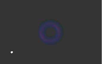
If you like, try manipulating the other parameters of the fog with the number box objects above the fog_params message.
Implementation Dependence Like antialiasing, which was introduced in Tutorial 33, the effects of fog parameters may vary from system to system, depending on what OpenGL renderer is being used. The basic characteristics of fog discussed above should be basically the same, but details such as how the density parameter affects the fog may vary.
Summary
We have described OpenGL’s lighting model and its implementation in Jitter in some detail. We discussed the specular, diffuse and ambient components of the GL lighting model, how they approximate different aspects of a real world scene, and how they combine to make an image. The distinction between positional and directional lighting was introduced. Finally, we saw how to add fog to a scene on an object-by-object basis.