Filter Tutorial 3: Analog-Style Synthesis
Now that we are familiar with some basic types of filters, we can think about different sounds to use with them. Most of the synthesis work we've looked at thus far has involved working with sinusoidal oscillators (the cycle~) object, creating complex spectra through different types of modulation synthesis (e.g. FM) or waveshaping. MSP has a number of oscillators that create more complex sounds on their own, and they are quite useful for creating richer sounds that can be shaped by filters. We'll introduce these oscillators here, briefly looking at a couple of objects that allow you to plot signal data along the way.
Waveforms
Look at the tutorial patcher. It consists of a kslider object controlling the frequencies of four different MSP objects: cycle~, tri~, saw~, and rect~. These oscillators each have their own volume control (a *~ object) that feeds them through a lores~ object to the dac~ and to a pair of graphical objects at the bottom. Some additional logic in the patcher exposes some other features of these oscillators.
- Start the audio in the tutorial patcher and pick a note on the kslider. One-by-one, turn up and listen to the different oscillators by adjusting thenumber boxobjects below each one. Listen to the sound, and look at the images that appear in the objects at the bottom of the patcher.
Our tutorial features four oscillators that are commonly used in analog sound generation and, as a result, are very common in digital synthesizers that are modeled on analog-style synthesizers from the 1960s and 1970s.
The cycle~ object, as we already know, generates a cosine wave which, when discussed in the context of a basic synthesizer setup, is indistinguishable from a sine wave. It generates a roller-coaster shaped waveform that is generated by solving a sine (or cosine) function on the angle of a line tracing a circle. The property of a sine wave that is of sonic interest is its spectrum; it contains only one frequency, and is the purest tone we can generate:

How to make a cosine wave, the Max way.
The phasor~ object generates a sawtooth waveform. This waveform is simply a rising ramp from 0 to 1 that repeats at a set frequency. It contains all the harmonics of the fundamental at a power equal to 1/n. Thus a 100 Hz sawtooth wave contains a 200 Hz tone at 1/2 volume, a 300 Hz tone at 1/3 volume, continuing on upwards:

A sawtooth (rising ramp) generator in Max.
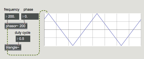
The triangle~ object converts the output of phasor~ into a triangular waveform. This triangle can be equilateral (i.e. the rising part of the ramp is the same percentage of the entire wave as the falling part), or it can be unequal. This proportion of rising versus falling is called the duty cycle of the waveform. In an equal triangle wave, the spectrum contains only odd harmonics, at a power of 1/n2, where n is the harmonic number. In other words, for a triangle wave at 100 Hz, we hear, in addition to the fundamental, a 300 Hz tone at 1/9th the volume of the fundamental, a 500 Hz tone at 1/25 the volume, a 700 Hz tone at 1/49th the volume, and so on:

Generating a triangle wave in Max.
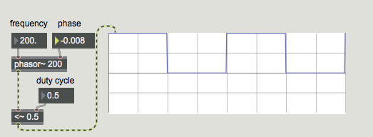
If we put a <~ or >~ object on the output of phasor~, the result is a pulse wave. This waveform is binary, consisting only of values 0 or 1. The duty cycle of a pulse wave controls the proportion of the wave that is negative versus positive. Like triangle waves, a duty cycle of 0.5 (square wave) only contains odd harmonics, but at a power of 1/n, resulting in stronger harmonic content than a triangle. A 100 Hz square wave contains a 300 Hz tone at 1/3 volume, a 500 Hz tone at 1/5 volume, etc.:

A square wave in Max with an even (0.5) duty cycle.
These waveforms are popular in synthesis design because they contain well- understood timbral properties that are easy to predict and, as a result, to manipulate through filtering. Mixing and matching these waveforms (often with slight detuning) allows us to create fairly rich synthesizer sounds reminiscent of classic analog synthesizers.
- Turn up one or more of our oscillators. At the right of the patcher, adjust the controls for the lores~ object, adjusting the dial and number box controlling the cutoff frequency and resonance of the filter. Listen to the result, and also look at its effect on the visuals at the bottom of the patcher.
scope~ ing things out
At the bottom of the tutorial patcher are two MSP user-interface objects that allow us to plot and view a signal. The top one is called the scope~ object, and it functions much like an analog oscilloscope, tracing the incoming signal across the X at a regular speed, with the amplitude of the waveform corresponding to the height (Y axis) of the line. Two number box objects attached to the scope~ control how many samples of audio it chunks into small buffers which it draws as line segments in the object. Adjusting those numbers allows us to get a more or less detailed view of the signal entering the object.
The second (lower) user interface object is called a spectroscope~ : it provides a different view of our signal: that of a spectrogram (or spectrum plot). The X axis of the graph corresponds not to time, but to frequency, with the Y axis showing the amplitude of the signal at that corresponding frequency.
-
One by one, turn up our waveforms and see how they 'look' in the scope~ and spectroscope~ objects. If the waveform in the scope~ seems to go by too quickly or slowly, adjust the number boxes attached to the object to see if you can 'tune in' a good setting for the waveform. (Hint: if you play an F, setting buffers per pixel at 4 and samples per buffer at 126 is pretty stable. You can get a rock steady display by tuning the oscillator frequency to 350 Hz.)
-
Using the controls for the lores~ object, change the amount of high frequencies filtered out in the sound, and see how that impacts on the waveform. Notice that the cycle~ object is largely immune to the effects of the lores~ object unless the cutoff frequency falls below its fundamental; this is because the sine wave only generates one frequency to begin with.
-
When listening to the tri~ and rect~ objects, adjust the number box labeled 'Duty cycle'. Lowering it towards
0or raising it towards1changes the balance of the harmonics in those two waveforms.
The many aliases of digital oscillators
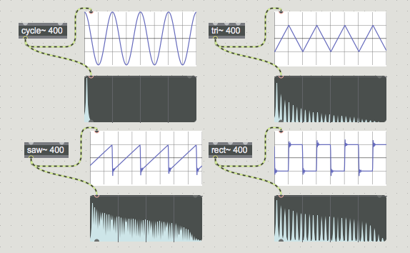
The waveforms described above are discussed as optimal shapes: when viewed, a triangle wave should look like a triangle, a sawtooth should resemble its namesake, and a square should look, well, square. Because of the implementation of these oscillators in a digital system, however, some changes are made to their shapes or, more accurately, the algorithms that generate their shapes. This is to avoid the higher harmonics of the mathematically accurate waveforms exceeding the Nyquist frequency of your audio hardware and folding over creating unpleasant artifacts. The upshot of this is that tri~, saw~, and rect~ are all anti-aliased (or band-limited) oscillators, and have slightly different shapes than the ideal, even though their generated spectra look (and sound) correct:

Sync or swim
- In the upper-right of the tutorial patcher, open the gate~ object by checking the toggle box. Set the frequency of the phasor~ to
1by typing into the number box connected to its inlet. Turn up the tri~ object, and turn down everything else. You should hear a 'jump' in the waveform once per second. Raise the frequency of the phasor~ by dragging in the number box. Once you get into the audible frequency range (around20Hz) you should notice the frequency of the phasor~ dominate over the frequency of the tri~ object. Try turning down the tri~ wave and turning up the saw~ and rect~. Notice that audible-range settings for the phasor~ seem to eliminate the audio from the square wave generator.
The three complex oscillators have an additional inlet that allows them to be synchronized by another oscillator. Every time the phasor~ object resets its phase (i.e. repeats its waveform), the oscillator receiving the 'sync' resets itself, i.e. starts drawing its shape over again. This technique of oscillator sync is useful for using one oscillator as a source of timbre ringing at the frequency of a second controlling oscillator. In this way, we could have a 200 Hz phasor~ signal controlling triangle, sawtooth, and square waves at different frequencies of their own, applying richness to the sound from the interaction of the two waveforms.
Summary
In addition to the cycle~ object, which produces a cosine wave, MSP has three other 'analog-style' antialiased oscillators: tri~, which produces a triangle wave, saw~, which generates a sawtooth wave, and rect~, which creates a square wave. Both tri~ and rect~ can have their duty cycles modified, and all three can receive 'sync' from another oscillator. The addition of a filter such as lores~ completes the "filtered beep" sound common to almost all synthesizers. The scope~ and spectroscope~ objects are very useful for viewing signal data, either unfolding in the time domain (scope~) or in the frequency domain (spectroscope~).