Video and Graphics Tutorial 8: Audio into a matrix
Intro
Whether it’s for installations or your next VJ set, audio-responsive visuals can be one of the most exciting aspects of working with real-time images in Max. In this section we will look at several ways of using sound in combination with Jitter.
Setup
To get started, set up the usual combination of a jit.world object with a named rendering context (we'll use jit.world loud here) and toggle, and add an ezadc~ object anywhere in your patch. The ezadc~ object lets use our built-in microphone as a source for live audio input.

If you’d rather work with audio samples, you can create an audio playlist~ object using the same technique as we used in the very first of these tutorials: Click on the audio icon (it's the eighth note directly above the video icon on the left sidebar) of your patcher window to show the Audio Browser, click on the name of an audio file and drag it from the browser to an empty spot in your patcher window to create a jit.playlist loaded with the audio you selected.
Amplitude
If you are looking for a one-to-one correlation between sound and changes in an image, amplitude (loudness) is often the simplest and most directly observable.
Create a peakamp~ object and connect its output to a flonum object. Connect the left outlet of ezadc~ to the left inlet of peakamp~. We're going to need a way to trigger readings from the peakamp~ object, so we'll connect the middle outlet of jit.world to the peakamp~ object's left inlet. Lock your patch, click on the toggle to turn on jit.world, and then the click on the ezadc~ object to turn audio on. Make some noise to see how your voice, typing, or sound in your environment translates into number values.
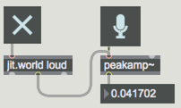
The peakamp~ object takes in a signal. Each time it receives a bang, it outputs the highest amplitude value received value since the last bang. The center outlet of jit.world object automatically sends out a bang each time it completes rendering a frame - so you automatically get one new value per frame, in sync with your frame rate.
Now that you have some values to work with, you can use the amplitude to control any aspect of your patch. Let’s start with something simple like adjusting brightness of incoming video. Add a jit.grab object with a message box containing the word open attached to its inlet, and a jit.brcosa with an attrui displaying brightness or contrast attributes to the upper and lower parts of your patch, respectively. Patch the output of jit.grab into jit.brcosa object's inlet, and the jit.brcosa object's outlet to the jit.world. Finally, connect the output of the peakamp~ to the inlet of the attrui. Click on the openmessage box to start the camera to see how the audio affects the brightness.
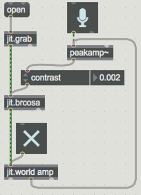
You can also use audio filters to extend what’s possible with amplitude control. By emphasizing or reducing certain frequencies of audio input, we can take a single input source and use it to control a variety of parameters. Let’s try this now with an svf~ filter (state-variable filter).
- Open
jitter_core_-_8_-_Audio_into_a_Matrix_3.maxpat
In this example, we take a drum sample and split it off into three filtered streams - a low pass, high-pass and bandpass - and use each of them to control aspects of the scale of an object created using jit.gl.gridshape.
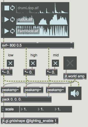
The low-end controls the x-scale of the object, the mids control the z-scale, and the high-end controls the y-scale. Try out the different sound files see how they affect the shape.
The raw output of peakamp~ can be offset, scaled and smoothed to achieve a variety of behaviors. Some objects to look at are scale, zmap (which scales an input and clips the low and high range) and slide.
Catching Audio
The jit.catch~ object allows us to sample incoming audio values and store them in a matrix. In our example, we use input signal data to manipulate a jit.gl.gridshape geometry matrix. Open up jitter_core_-_8_-_Audio_into_a_Matrix_1.maxpat. Click on the jit.world object's toggle and the ezdac~ to start things up, then select an audio source and begin playback to see the patch in action.
Let’s walk through the patch: The audio data is connected directly to jit.catch~ - one of a few Jitter objects made to work directly with signal data.
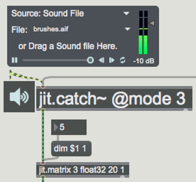
Each time it receives a bang, the jit.catch~ object outputs the most recent frame of audio samples as a 1-plane matrix containing float32 (32-bit floating point) number values. Since our audio data is now converted into a regular jitter matrix, we can use other Jitter objects to perform operations on it.
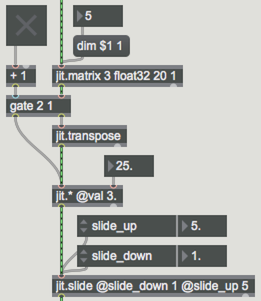
Sending the output of the jit.catch~ object to a jit.matrix object lets us adjust the output dimensions of the matrix, which will control the resolution of the changes made to the final form. Try adjusting the number value connected to the dim $1 1message box and see how it interacts. Lower dim values affect larger regions of the form, while higher values are more subtle. The matrix data then passes a gate object with an optional jit.transpose. Toggle the gate on/off to select which dimension is affected by the audio matrix. Next, the matrix passes through a jit.* object that scales how much the audio affects the image. The jit.slide eases the changes in data over time.
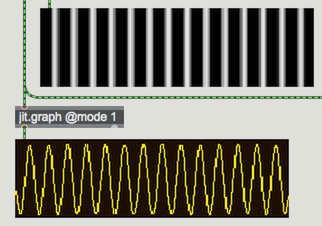
The final output of our audio matrix is being displayed in a jit.pwindow as both raw matrix data and also as output formatted by a jit.graph object. Audio signal values are typically represented using data in the range of -1. to 1. (i.e. both positive and negative). In the raw form negative number values are represented as black in jit.pwindow. By converting the values for display with jit.graph object, we get a meaningful representation of both positive and negative values.
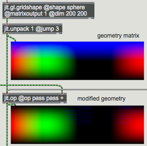
To the right is the jit.gl.gridshape @matrixoutput 1 object (setting the matrixoutput attribute will output the object as a matrix). The resulting matrix contains more planes of data than we really need for our patch, so we use the jit.unpack 1 @jump 3 object to grab only the parts of the geometry matrix we are interested in - the x, y and z coordinates. The two matrices are combined using a jit.op object and then sent into a jit.gl.mesh object to be drawn. The default behavior for jit.op object is to pass the first two planes (x and y) unaltered and add the audio data to the z plane. Try some other options by clicking the various op messages.
Try manipulating the settings in the patch and use a variety of input sources to see what’s possible.
Explore Further
Visualization of audio signals is a complex area of study and the methods that we have looked at are just a few possibilities. Some good places to explore more in this territory are the Jitter Recipes. Also, take a look through the Jitter examples to be found in the File Browser. Some other objects worth exploring in this area are jit.poke~ and jit.peek~, as well as jit.buffer~ and jit.release~.